
Handling system for in-core detector thimble tube of reactor

Inactive Publication Date: 2009-02-26
KOREA HYDRO & NUCLEAR POWER CO LTD
View PDF4 Cites 5 Cited by
  • Summary
  • Abstract
  • Description
  • Claims
  • Application Information

AI Technical Summary

Benefits of technology

[0008]Therefore, the present invention has been made in view of the above problems, and it is an object of the present invention to provide a handling system for an in-core detector thimble tube of a reactor, which can automatically withdraw or retract the in-core detector thimble tube without any damage to the thimble tube, thereby achieving several advantages including an extended thimble tube exchange interval, improved safety of system facilities, reduced labor costs and working time, and reduced worker radiation exposure, shortened precaution / maintenance period, and enhanced reactor use efficiency.
[0009]In accordance with the present invention, the above and other objects can be accomplished by the provision of a handling system for an in-core detector thimble tube of a reactor, which provides a movement path of a movable detector used to measure a neutron flux within the reactor, the handling system comprising: a withdrawing / retracting device to grip the thimble tube using synthetic resin pinch rollers so as to withdraw and retract the thimble tube without any damage to the thimble tube; a thimble tube tensioning device to apply a constant tensile force to the thimble tube so as to prevent the thimble tube from shaking or bending upon withdrawing / retracting operations of the thimble tube; and a platform to temporarily keep the withdrawn thimble tube at a fixed position, to prevent shaking of the thimble tube, and to provide a movement path of the thimble tube tensioning device. The handling system can stably manage the thimble tube that is an important component in terms of safety, serving to maintain a pressure boundary of a reactor coolant system.
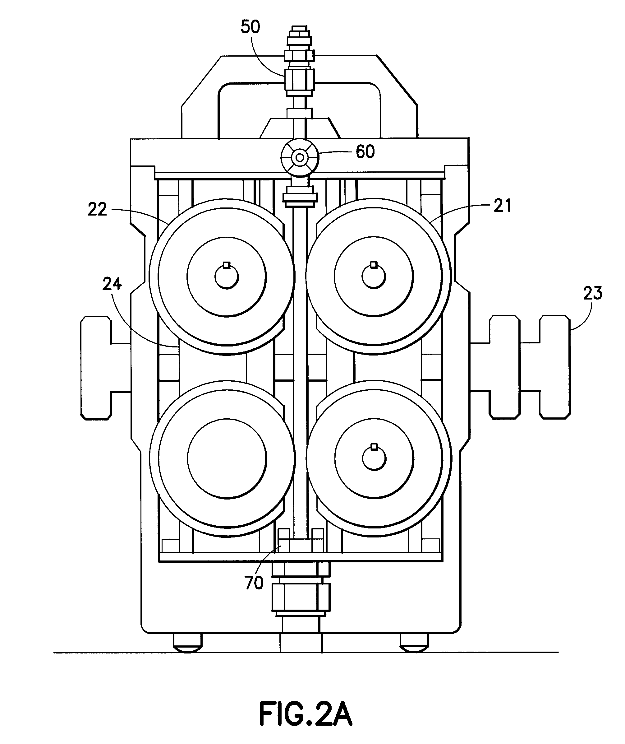
[0010]The withdrawing / retracting device may include: a body frame; a seal table disposed below the body frame and used to support the withdrawing / retracting device mounted thereon; a T-shaped clamp to mount the withdrawing / retracting device on the seal table; two upper and lower driving compression pinch rollers to be driven by two motors for increasing a thimble tube withdrawing / retracting force; two upper and lower idle compression pinch rollers to be driven by rotation of the driving compression pinch rollers; and a thimble tube clamping mechanism to grip the thimble tube in a roller compression manner via operation as screw nuts having clockwise and counterclockwise threads are tightened by a manually operable rotating handle. Automatic withdrawal / retraction of the thimble tube is possible, providing several advantages including reduced labor costs and working time, reduced worker radiation exposure, shortened precaution / maintenance period, and enhanced reactor use efficiency.

Problems solved by technology

However, no nuclear power plants have a system to withdraw and retract a thimble tube using automated facilities.
Furthermore, thimble tube withdrawing / retracting operations are generally performed in a high radiation area located within a reactor pressure vessel and therefore, the worker is exposed to excessive radiation.
In addition, during the thimble tube withdrawal / retraction operations, maintaining a constant vertical grip force is actually difficult due to poor working environment.
Therefore, a specific portion of the thimble tube, to which the worker's grip force is applied, is inevitably bent and the bent portion of the thimble tube is again spread upon retraction.
With repeated bending and spreading operations, the thimble tube has a high risk of breakage.

Method used


Image

  • Handling system for in-core detector thimble tube of reactor
  • Handling system for in-core detector thimble tube of reactor
  • Handling system for in-core detector thimble tube of reactor

Examples


Embodiment Construction

[0024]The present invention relates to a thimble tube withdrawing / retracting system for withdrawing and retracting a thimble tube, which provides a movement path of a movable detector used to measure a neutron flux within a pressurized light water reactor. Now, the overall configuration of the system will be described.

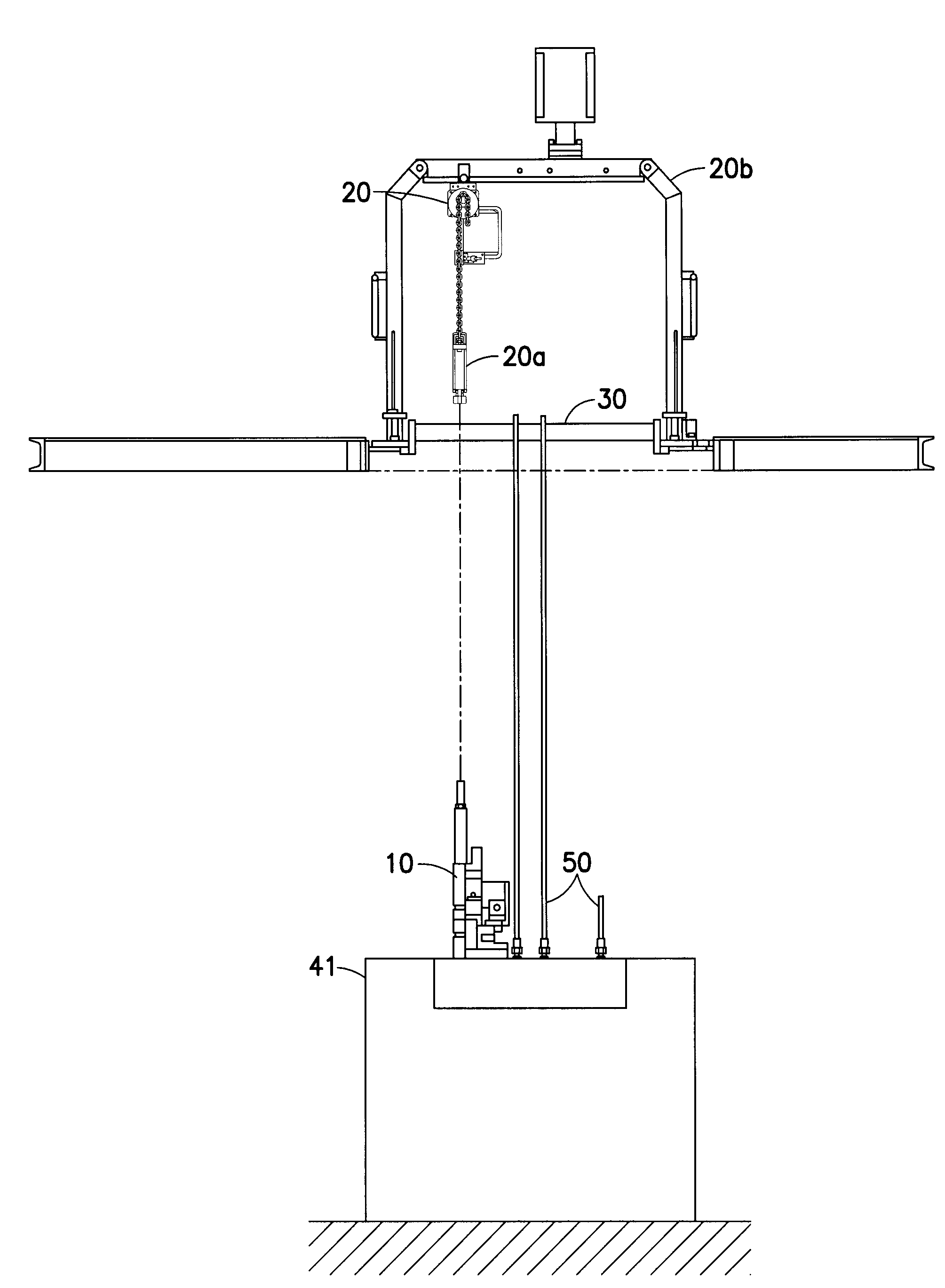
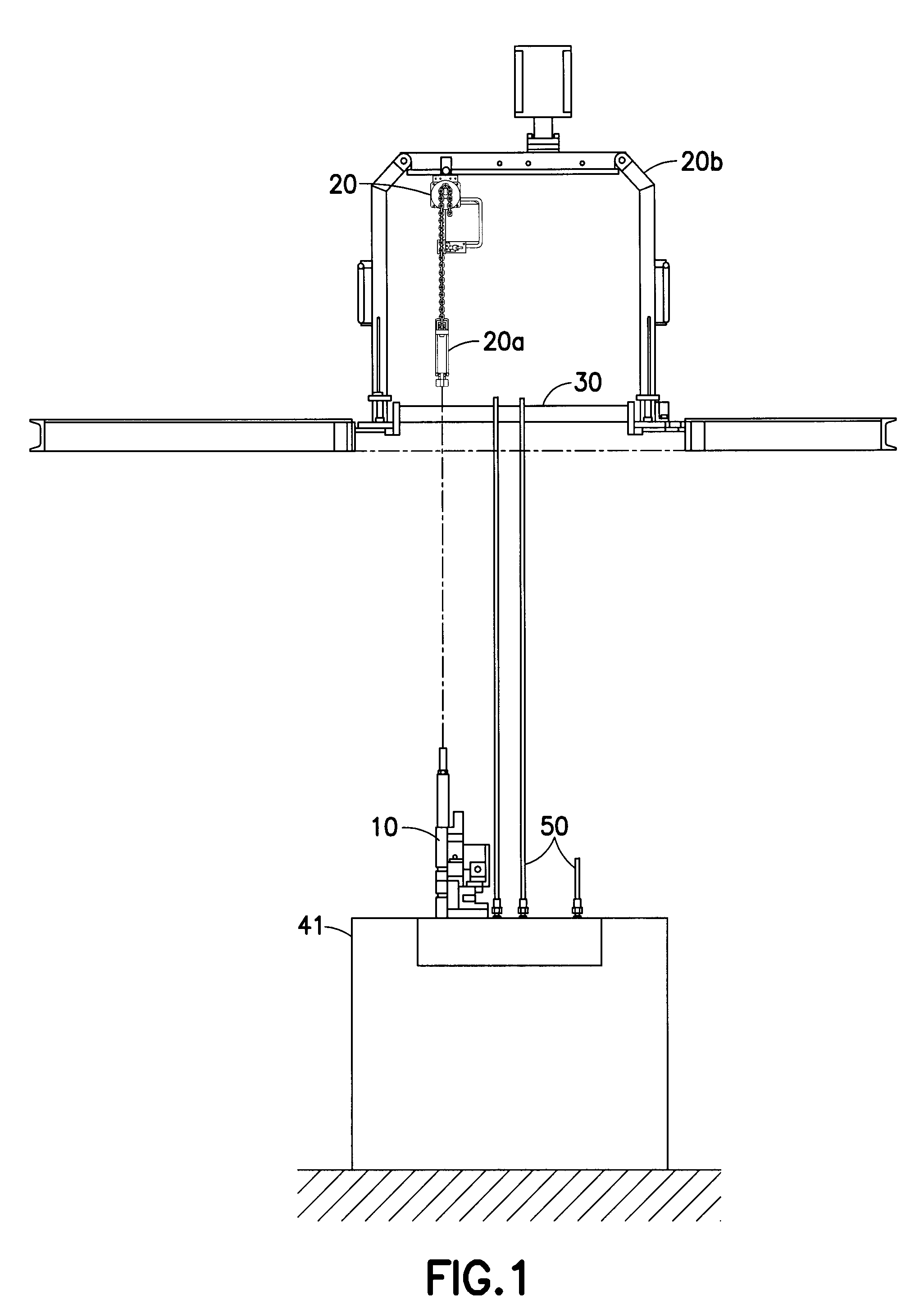
[0025]Referring to FIG. 1, the overall system broadly includes a thimble tube withdrawing / retracting device 10, a thimble tube tensioning device 20, and a thimble tube platform 30. The thimble tube withdrawing / retracting device 10 is used to grip each thimble tube 50 on a seal table 41, so as to withdraw and retract the thimble tube 50. The thimble tube tensioning device 20 is used to apply a tensile force to a distal end of the thimble tube 50, so as to prevent the thimble tube 50 from shaking upon withdrawing / retracting operations. The thimble tube platform 30 is used to stably dispose the withdrawn thimble tube 50 thereon. Here, the thimble tube tensioning device 20...


PUM


Abstract

A handling system for an in-core detector thimble tube of a reactor is disclosed. The handling system serves to withdraw and retract a thimble tube so as to provide a movement path of a movable detector used to measure a neutron flux within a reactor. For this, the handling system basically includes a thimble tube withdrawing / retracting device, which grips the thimble tube using a plurality of synthetic resin pinch rollers to withdraw and retract the thimble tube without any damage to the thimble tube, a thimble tube tensioning device, which applies a constant tensile force to the thimble tube to prevent the thimble tube from shaking or bending upon withdrawing / retracting operations, and a thimble tube platform, which temporarily keeps the withdrawn thimble tube at a fixed position without a risk of shaking of the thimble tube and provides a movement path of the thimble tube tensioning device. With automatic withdrawal / retraction of the thimble tube without damage provides advantages of an extended thimble tube exchange interval, improved safety of system facilities, reduced labor costs and working time, and reduced worker radiation exposure, shortened precaution / maintenance period, and enhanced reactor use efficiency.

Description

BACKGROUND OF THE INVENTION[0001]1. Field of the Invention[0002]The present invention relates to a handling system for an in-core detector thimble tube of a reactor, and more particularly, to a handling system for an in-core detector thimble tube of a reactor, which can automatically withdraw or retract the in-core detector thimble tube without any damage to the thimble tube, thereby achieving several advantages including an extended thimble tube exchange interval, improved safety of system facilities, reduced labor costs and working time, and reduced worker radiation exposure, shortened precaution / maintenance period, and enhanced reactor use efficiency.[0003]The present invention provides a system capable of gripping, withdrawing and retracting an in-core detector thimble tube of a reactor for the purpose of automatic guidance of the thimble tube, and belongs to a mechanical appliance design in the field of mechatronics.[0004]2. Description of the Related Art[0005]A nuclear measure...

Claims


Application Information

Patent Timeline
IPC IPC(8): G21C17/108
CPCG21C17/108G21C19/207G21C19/02Y02E30/30G21C19/20
Inventor LEE, JAE-KYUNGCHO, BYUNG-HAKPARK, JOON-YOUNGBYUN, SEUNG-HYUNSHIM, MYUNG-JURHO, BYUNG-TAE
Owner KOREA HYDRO & NUCLEAR POWER CO LTD
Learn More