
Methods for formation of an ophthalmic lens precursor and lens

a technology of precursor and lens, applied in the field of ophthalmic lens fabrication apparatus, can solve the problems of difficult to form custom lenses specific to a particular patient's eye or a particular application, high modulus of lathing, consumption and limited scope, etc., and achieve the effect of high quality

Active Publication Date: 2009-02-26
JOHNSON & JOHNSON VISION CARE INC
View PDF100 Cites 71 Cited by
  • Summary
  • Abstract
  • Description
  • Claims
  • Application Information

AI Technical Summary

Benefits of technology

[0025]Apparatus of implementing the methods described herein are further disclosed in the copending application entitled “Apparatus for Formation of an Ophthalmic Lens Precursor and Lens” filed concurrently herewith.
[0026]Accordingly, the present invention includes an methods for forming a customized contact lens, with varied optical performance and with varied non-optical characteristics in a flexible and programmable manner. An ophthalmic lens results comprising a varied material nature; including a hydrogel lens, and in some embodiments, a silicone hydrogel lens.

Problems solved by technology

However, the nature of the injection molding processes and equipment make it difficult to form custom lenses specific to a particular patient's eye or a particular application.
However, lathing requires a high modulus lens material, is time consuming and limited in the scope of the surface available and stereo lithography has not yielded a lens suitable for human use.

Method used


Image

  • Methods for formation of an ophthalmic lens precursor and lens
  • Methods for formation of an ophthalmic lens precursor and lens
  • Methods for formation of an ophthalmic lens precursor and lens

Examples


example 1

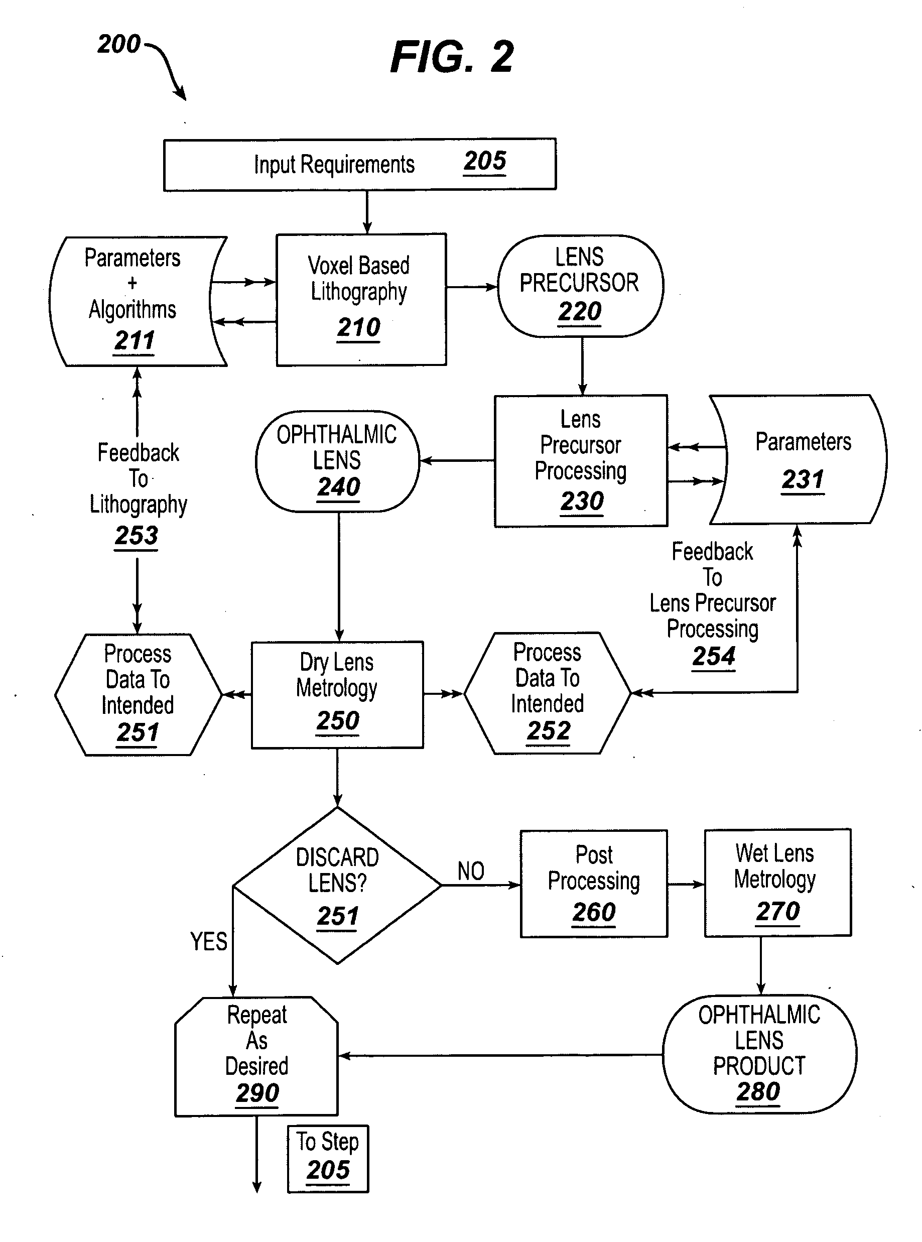
[0220]Various embodiments of the invention have been practiced and lens products and Lens Precursors of the forms discussed herein have been produced. In this section a discussion of results from one set of embodiments is given as an example.

[0221]The apparatus for performing the results in this example comprised the following general aspects. A Voxel-based lithography optical apparatus was used to form a Lens Precursor. This apparatus, from a general perspective, was comprised with a light source of the preferred embodiment type operating at 365 nm. A homogenizer with an optical pipe and focusing optics, as discussed was used to illuminate the Texas Instruments DLP™ XGA Digital Mirror Device. The imaging system further comprised focusing optics onto a forming optic of the type depicted in FIG. 10.

[0222]The intensity profile and DMD pixel values were calculated based on the optical absorbance and reactivity of the reactive monomer mixture which was comprised of Etafilcon A. This sys...

example 2

[0246]In this section a description of a specific embodiment alternative for a forming optic component 580 is given in FIG. 181800. Again, the forming optic is the support upon which a Lens Precursor or lens may be built. Its depiction as 1000, FIG. 10, may be the most straightforward for this discussion. FIG. 10, in one embodiment described already, may depict a solid optic of substantial mass 1010, with an optical grade surface formed upon it 1011. The alternative embodiment 1800, discussed here replaced the massive element 1010, with a mold piece 1810, that may be much like mold pieces commonly comprising the volume production of standard ophthalmic lenses by current production standards. In such a case the mold piece may have been formed by injection molding to a standard optical form.

[0247]The resulting plastic form could have additional shaping around the optical surface, which is similar to 1011, comprising a well surrounding the optical surface 1860. Additional complexity ma...


PUM

PropertyMeasurementUnit
transmittanceaaaaaaaaaa
full width at half maximum breadthaaaaaaaaaa

Abstract

This invention discloses methods for generating one or both of an ophthalmic lens precursor with at least a portion of one surface free-formed from a Reactive Mixture. In some embodiments, an ophthalmic lens precursor is formed on a substrate with an arcuate optical quality surface via a source of actinic radiation controllable to cure a definable portion of a volume of Reactive Mixture.

Description

CROSS REFERENCE TO RELATED APPLICATIONS[0001]The present application claims priority to Provisional Patent Application Ser. No. 60 / 957,069 filed, Aug. 21, 2007 and entitled, “Customized Ophthalmic Lens Fabrication” the contents of which are relied upon and incorporated by reference.FIELD OF USE[0002]This invention describes apparatus for the fabrication of ophthalmic lenses and, more specifically, in some embodiments, the fabrication of a Lens Precursor useful for the formation of a customized contact lenses.BACKGROUND OF THE INVENTION[0003]Ophthalmic lenses are often made by cast molding, in which a monomer material is deposited in a cavity defined between optical surfaces of opposing mold parts. Multi-part molds used to fashion hydrogels into a useful article, such as an ophthalmic lens, can include for example, a first mold part with a convex portion that corresponds with a back curve of an ophthalmic lens and a second mold part with a concave portion that corresponds with a fron...

Claims


Application Information

Patent Timeline
Patent Type & Authority Applications(United States)
IPC IPC(8): B29D11/00
CPCB29C35/0888B29D11/00442B29D11/00144G02C7/04B33Y80/00B29D11/00038B29D11/00153
Inventor WIDMAN, MICHAEL F.ENNS, JOHN B.POWELL, P. MARKSITES, PETER W.
Owner JOHNSON & JOHNSON VISION CARE INC
Learn More