
Method for removing surface deposits and passivating interior surfaces of the interior of a chemical vapor deposition reactor

a technology of chemical vapor deposition reactor and interior surface, which is applied in the direction of detergent compounding agents, non-surface active detergent compositions, other chemical processes, etc., can solve the problems of reducing the productive capacity of the chamber, the need to clean the chamber regularly, and the effect of cleaning gases being limited

Inactive Publication Date: 2009-02-19
MASSACHUSETTS INST OF TECH
View PDF10 Cites 193 Cited by
  • Summary
  • Abstract
  • Description
  • Claims
  • Application Information

AI Technical Summary

Benefits of technology

[0003]The present invention provides effective methods for removing surface deposits from the interior of a CVD reactor using novel cleaning gas mixtures and activated cleaning gas mixtures. The methods of the invention include, but are not limited to, the steps of providing a gas mixture, activating the gas mixture in a remote chamber or in a process chamber to form an activated gas mixture, where the gas mixture comprises a source of at least one atom selected from the group consisting of carbon and sulfur, NF3, and optionally, an oxygen source, wherein the molar ratio of oxygen:carbon source is at least 0.75:1; and contacting the activated gas mixture with surface deposits within the CVD reactor. The gas mixtures of the present invention include, but are not limit

Problems solved by technology

One of the problems facing the operators of chemical vapor deposition reactors is the need to regularly clean the chamber to remove deposits from the chamber walls and platens.
This cleaning process reduces the productive capacity of the chamber since the chamber is out of active service during a cleaning cycle.
Present cleaning gases are believed to be limited in their effectiveness due to low etch rates.
In order to partially obviate this limitation, current gases need to be run at an inefficient flow rate, e.g. at a high flow rate, and thus greatly contribute to the overall operating cost of the CVD reactor.
In turn this increases the production cost of CVD wafer products.

Method used


Image

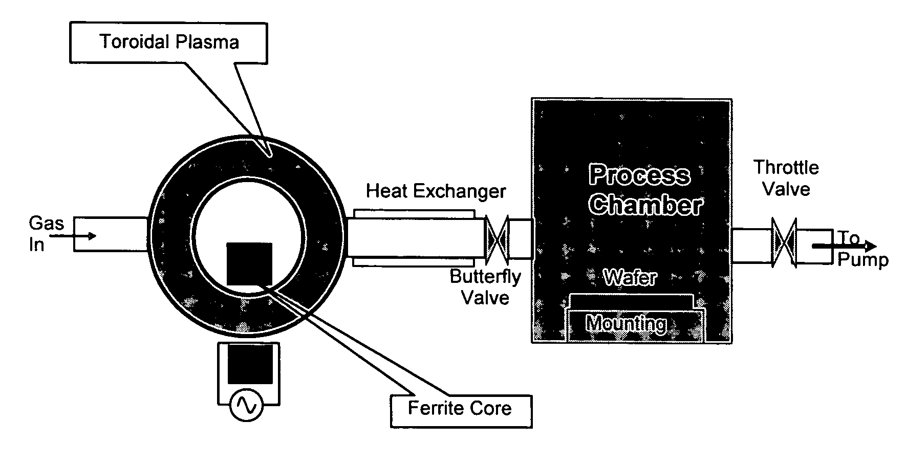
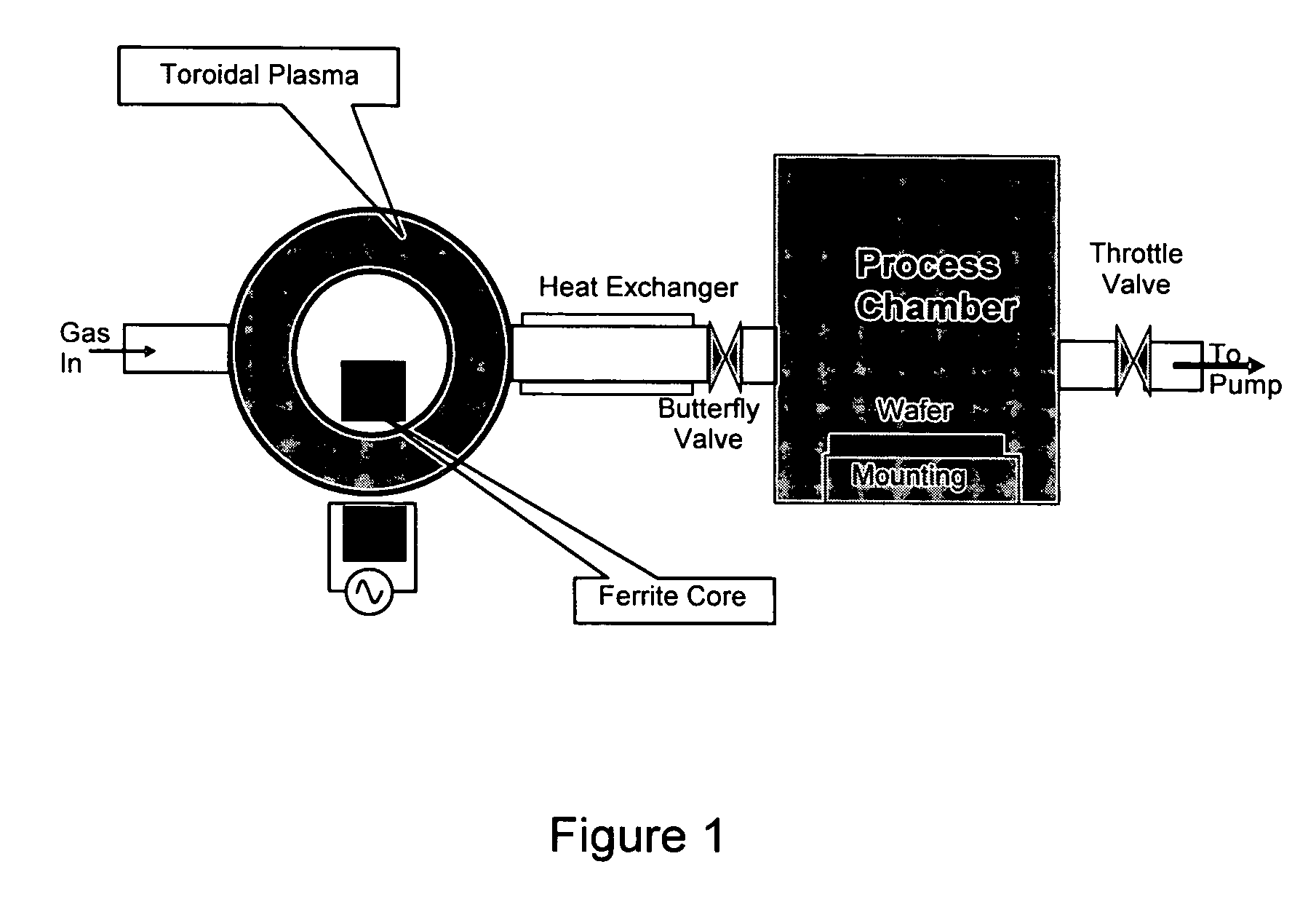
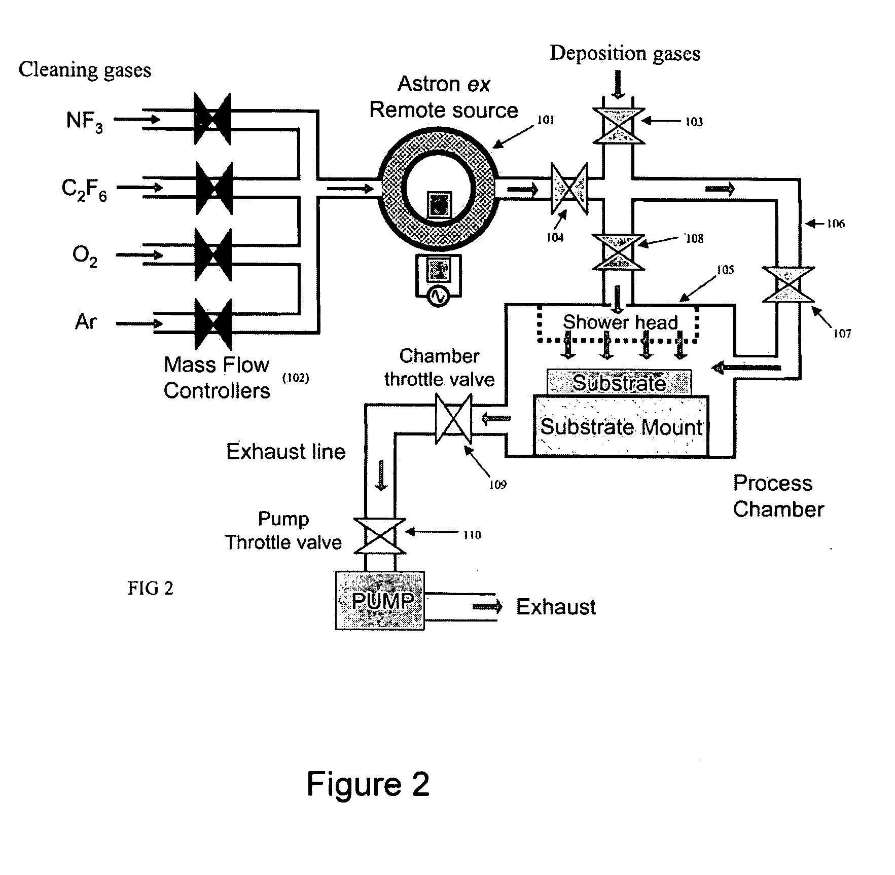
  • Method for removing surface deposits and passivating interior surfaces of the interior of a chemical vapor deposition reactor
  • Method for removing surface deposits and passivating interior surfaces of the interior of a chemical vapor deposition reactor
  • Method for removing surface deposits and passivating interior surfaces of the interior of a chemical vapor deposition reactor

Examples


example 1

[0037]This example illustrates the effect of the addition of fluorocarbon on the silicon nitride etch rate in NF3 systems with oxygen at different gas compositions and different wafer temperatures. In this experiment, the feed gas was composed of NF3, oxygen and C2F6. Process chamber pressure was 5 torr. Total gas flow rate was 1700 sccm, with flow rates for the individual gases set proportionally as required for each experiment. By way of illustration, in the experiment with 9% oxygen, 9% C2F6, and 82% NF3, the oxygen flow rate was 150 sccm, the C2F6 flow rate was 150 sccm, and the NF3 flow rate was 1400 sccm. The feeding gas was activated by the 400 kHz 5.9-8.7 kW RF power. The activated gas then entered the process chamber and etched the silicon nitride surface deposits on the mounting with the temperature controlled at 50° C. As shown in FIG. 3, when 3.5 mole percent oxygen and 2.3 mole percent fluorocarbon were added, the etch rate was over 2500 A / min, and exhibited low sensiti...

example 2

[0038]This example illustrated the effect of the addition of fluorocarbon on the silicon nitride etch rate in NF3 systems with oxygen and the reduced effect of source pressure on etch rate. The results are illustrated in FIG. 4. In this experiment, the feed gas was composed of NF3, optionally with O2 and optionally with C2F6. Process chamber pressure was 2 torr. Total gas flow rate was 1700 sccm, with flow rates for the individual gases set proportionally as required for each experiment. By way of illustration, in the experiment with 9% oxygen and 91% NF3, the NF3 flow rate was 1550 sccm and the oxygen flow rate was 150 sccm. The feeding gas was activated by the 400 kHz 5.0˜9.0 kW RF power to a neutral temperature of more than 3000 K. The activated gas then entered the process chamber and etched the silicon nitride surface deposits on the mounting with the temperature controlled at 50° C. As shown in FIG. 3, when 9 mole percent fluorocarbon and 9 mole percent oxygen were added to NF...

example 3

[0039]This example illustrates the effect of the addition of C2F6 on the silicon nitride etch rate in mixtures of NF3 and oxygen with a chamber pressure of 3.0 torr. Total gas flow rate was 1700 sccm. The results are illustrated in FIG. 5. The feeding gas was activated by the 400 kHz 4.6 Kw RF power to a neutral temperature of more than 3000 K. As the results indicate, when 9 mole percent C2F6 is added to the feed gas, i.e. the feed gas mixture was composed of 9 mole percent C2F6, 9 mole percent oxygen and 82 mole percent NF3, the etching rate of silicon nitride increase to from about 2200 A / min to about 2450 A / min, and exhibited lower variation with variations in source pressure.


PUM

PropertyMeasurementUnit
Fractionaaaaaaaaaa
Fractionaaaaaaaaaa
Fractionaaaaaaaaaa

Abstract

The present invention relates to plasma cleaning methods for removing surface deposits from a surface, such as the interior of a depositions chamber that is used in fabricating electronic devices. The present invention also provides gas mixtures and activated gas mixtures which provide superior performance in removing deposits from a surface. The methods involve activating a gas mixture comprising a carbon or sulfur source, NF3, and optionally, an oxygen source to form an activated gas, and contacting the activated gas mixture with surface deposits to remove the surface deposits wherein the activated gas mixture acts to passivate the interior surfaces of the apparatus to reduce the rate of surface recombination of gas phase species.

Description

FIELD OF THE INVENTION[0001]The present invention relates to methods for removing surface deposits by using an activated gas mixture created by activating a gas mixture that includes a nitrogen source, a carbon or sulfur source, and a optionally, an oxygen source, as well as the gas mixtures and activated gases used in these methods.BACKGROUND OF THE INVENTION[0002]One of the problems facing the operators of chemical vapor deposition reactors is the need to regularly clean the chamber to remove deposits from the chamber walls and platens. This cleaning process reduces the productive capacity of the chamber since the chamber is out of active service during a cleaning cycle. The cleaning process may include, for example, the evacuation of reactant gases and their replacement with an activated cleaning gas followed by a flushing step to remove the cleaning gas from the chamber using an inert carrier gas. The cleaning gases typically work by etching the contaminant build-ups from the in...

Claims


Application Information

Patent Timeline
IPC IPC(8): C23C16/511C23C16/513C09K3/00B08B5/00C11D3/02C11D3/16C11D3/20
CPCB08B7/0035H01J37/32862C23C16/4405
Inventor SAWIN, HERBERT H.BAI, BOAN, JU JIN
Owner MASSACHUSETTS INST OF TECH
Learn More