
Fluid dynamic bearing device

a dynamic bearing and fluid technology, applied in the direction of sliding contact bearings, mechanical energy handling, mechanical equipment, etc., can solve the problems of increasing the number of parts and assembling man-hours, difficult to obtain high-quality bearing gaps, and difficult to form resin-based parts at high accuracy, so as to achieve high bearing performance and high accuracy , the effect of low cos

Inactive Publication Date: 2009-02-19
NTN CORP
View PDF17 Cites 41 Cited by
  • Summary
  • Abstract
  • Description
  • Claims
  • Application Information

AI Technical Summary

Benefits of technology

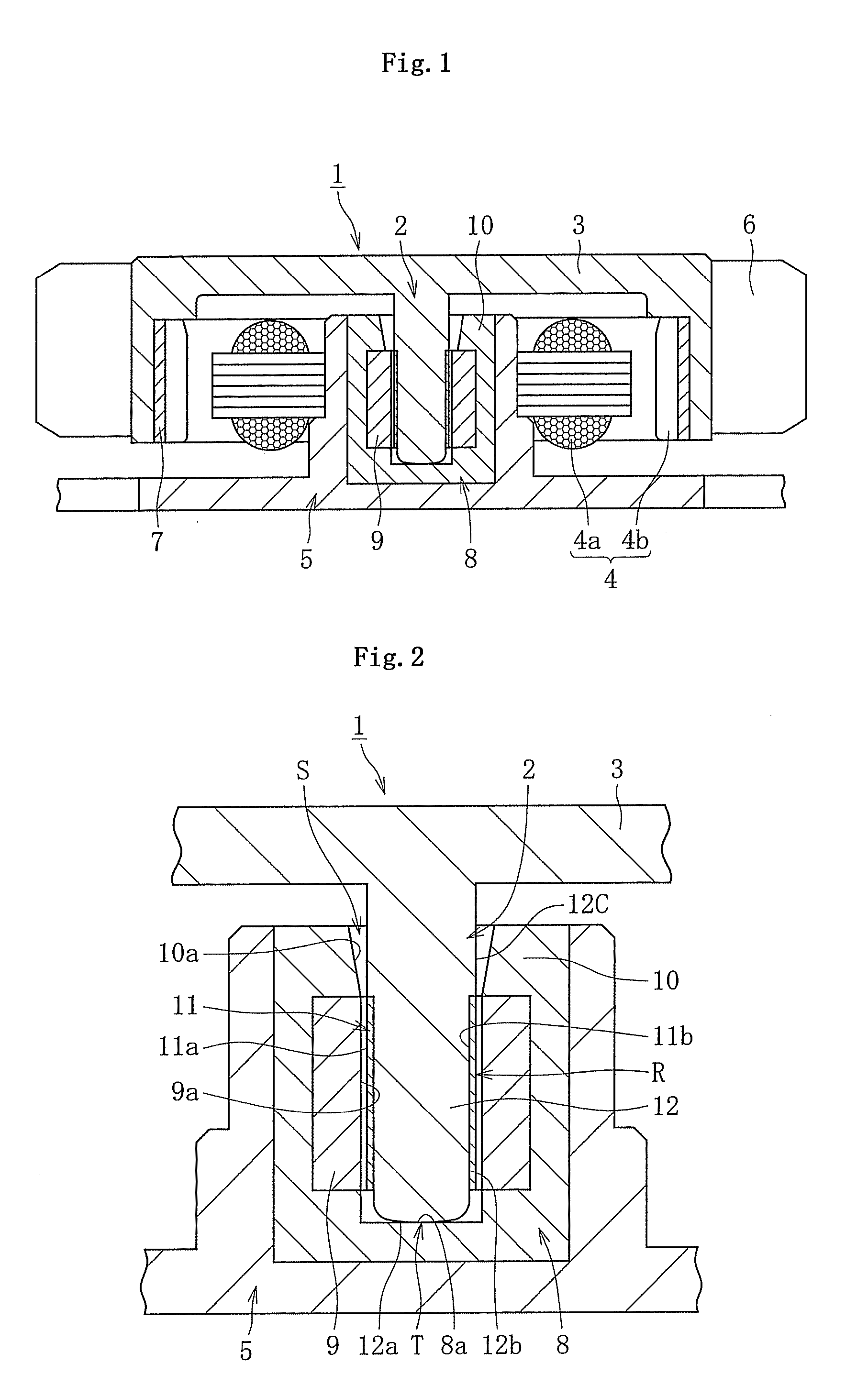
[0060]As mentioned above, by forming the region of the component constituting at least one of the fixed member and the rotational member, which faces the bearing gap, of the metal plated portion, a fluid dynamic bearing device which can produce high bearing performance by forming a bearing gap at high accuracy can be provided at low costs.
[0061]As mentioned above, by forming the sealing gap and the lubricant reservoir between the protrusion formed on the bearing member and the shaft member, a fluid dynamic bearing device which has good sealing property, lubricity, and long life can be provided at low costs.
[0062]As mentioned above, by forming the hydrodynamic pressure producing part by molding the resin with the insert inserted thereinto, and providing, in the hydrodynamic pressure producing part, the first region provided on the insert and made of a material different from the resin subjected to molding and the second region made of the resin, a hydrodynamic pressure producing part of the hydrodynamic bearing device can be obtained at high accuracy and at low costs.
[0063]As mentioned above, by employing the constitution in which the resin on the outer periphery of the metal part is orientated in the axial direction, the dimensional stability of the fluid dynamic bearing device having a resin portion, in particular the dimensional stability in the axial direction, can be improved.

Problems solved by technology

One may consider forming the bearing sleeve of the same kind of resin to maintain the bearing gap, but it is difficult to form parts made of a resin at high accuracy since the molding dimensions (dimensions of molds) of such parts need to be set considering shrinkage during molding.
When the components which form the bearing gap are both formed of a resin, it is even more difficult to obtain the bearing gap at high accuracy because of the influence of molding dimensional variation of both components.
Of course, the problem of this type can occur when components on the bearing side such as the bearing sleeve are formed of a resin in order to achieve cost reduction.
Moreover, cost reduction / sealing property tradeoffs entail the following problem: that is, since the various kinds of motors mentioned above extremely dislikes contamination by the lubricant, a sealing gap for preventing leakage of the lubricant is usually provided at the opening of the bearing member.
However, as in the above Patent document 4, when the sealing gap and the oil reservoir are formed between a component provided separately from the bearing member and the shaft member, the number of parts and assembling man-hours are increased, which inevitably increases the cost.
Moreover, accuracy / cost tradeoffs in the hydrodynamic pressure producing part entail the following problem: That is, as a fluid dynamic bearing device of this type, for example, Japanese Unexamined Patent Publication No. 2005-321089 (Patent document 5) discloses a fluid dynamic bearing device (hydrodynamic bearing device) which supports the shaft member in the radial direction in a non-contact manner by the hydrodynamic effect of the fluid occurring in the radial bearing gap between the inner circumferential surface of the bearing and the outer circumferential surface of the shaft member.
Therefore, when the mold is released from the inner periphery of the bearing, the molding portion of the mold and the hydrodynamic grooves of the bearing may interfere with each other, thereby damaging the hydrodynamic grooves.
Moreover, the dimensional stability / cost reduction tradeoffs of the fluid dynamic bearing device having a resin portion entail the following problem: That is, for example, Japanese Unexamined Patent Publication No. 2003-56552 (Patent document 7) discloses a bearing part used for a fluid dynamic bearing device of this type which is produced by insert-molding a cylindrical metal part (electroformed part) having an inner hole using a resin.
A bearing part made of resin has the advantage of being lighter and more economical than that made of metal, while it has the disadvantage of large dimensional change due to thermal shrinkage and other causes.
However, a change in the axial direction of the bearing part is unavoidable, and thus sink marks and other problems due to a difference in a dimensional change occur, which may adversely affect the axial dimension and accuracy of the bearing face.
Therefore, adherence force is reduced between itself and the metal plated portion formed on the outer periphery of the resin portion, which may lead to fallout of the resin part in some cases.
However, resins inevitably undergo molding shrinkage, and to obtain a desired bearing gap width, especially in a region which serves as the bearing face, needs precise finishing processes.
Therefore, forming bearing members of resins cannot produce sufficient cost merit.
Moreover, as stated above, resins generally have greater linear expansion coefficients than metals, and are susceptible to changes in temperature when the bearing is in operation.
Furthermore, resins have lower abrasion resistance than metals, and abrasion of the bearing face easily proceeds due to the sliding contact with the shaft member in particular at the time of starting, stopping and the like.
Generation of such negative pressure may cause bubbles and leakage of lubricating oil, which may lower bearing performance.
However, they are rather more easily worn depending on the difference of their hardness, and rotational accuracy may be thus lowered.
Moreover, when the difference in hardness between the two components is less than 100 Hv, failure mode when applied an impact load because of disturbance and the like is the stopping of relative motion as the result of interfacial friction, which may cause the stopping of the bearing (locking).
In general, metals which can form the electroformed part are limited and their hardness adjustment is difficult, but hardness adjustment of the shaft can be performed relatively easily and at high accuracy.
Moreover, when the hardness of the radial bearing face itself is lower than 350 Hv, scratches and strike marks are produced on the radial bearing face when integrated and at other occasions to possibly lower the precision of the bearing face, and handling thereof needs extra care.
These recesses can be formed by rolling, etching, cutting or other means, but it is desirably formed by rolling, considering processing accuracy and processing cost.
However, it is generally difficult to form a highly accurate recess on a hardness layer having a hardness of 400 Hv or higher by rolling.
Therefore, when a technique which requires carburizing, quenching and other heat treatment which are conducted at a high temperature is employed in case where recesses of this type are provided especially on the radial bearing face, deformation of the shaft material and lowered accuracy of the form of the recesses resulting from the deformation may be caused.
Moreover, DLC requires great cost.
However, since cutting has the risk of lowering the bearing performance due to the cutting powder produced during the process which may serve as contamination, cutting powder must be carefully removed, which raises processing cost.
Therefore, the problem of contamination associated with the cutting powder and thus increased processing cost are not caused.

Method used


Image

  • Fluid dynamic bearing device
  • Fluid dynamic bearing device
  • Fluid dynamic bearing device

Examples


example 1

[0178]To demonstrate the advantages of the invention according to this embodiment, abrasion test was performed in the mode shown in FIG. 26A. Abrasion test is a simplified test carried out by sliding rotating a body of rotation 291 corresponding to the electroformed part 204 under certain conditions (conditions similar to those under which the fluid dynamic bearing device is used) relative to a test piece 290 corresponding to the shaft member 202 shown in FIG. 19A to determine the amount of abrasion of the test piece 290 and the body of rotation 291. As the test piece 290, nine types of test pieces in which at least the surfaces slid against the body of rotation 291 are formed so as to have the hardnesses of 200 Hv, 280 Hv, 350 Hv, 520 Hv, 650 Hv, 920 Hv, 1180 Hv, 1530 Hv, and 1700 Hv were prepared. The number of samples of each test piece 290 is N=10, and the amount of abrasion shown in FIG. 26B is the average value thereof. As the body of rotation 291, one that is formed so as to ...


PUM

PropertyMeasurementUnit
Thicknessaaaaaaaaaa
Pressureaaaaaaaaaa
Diameteraaaaaaaaaa

Abstract

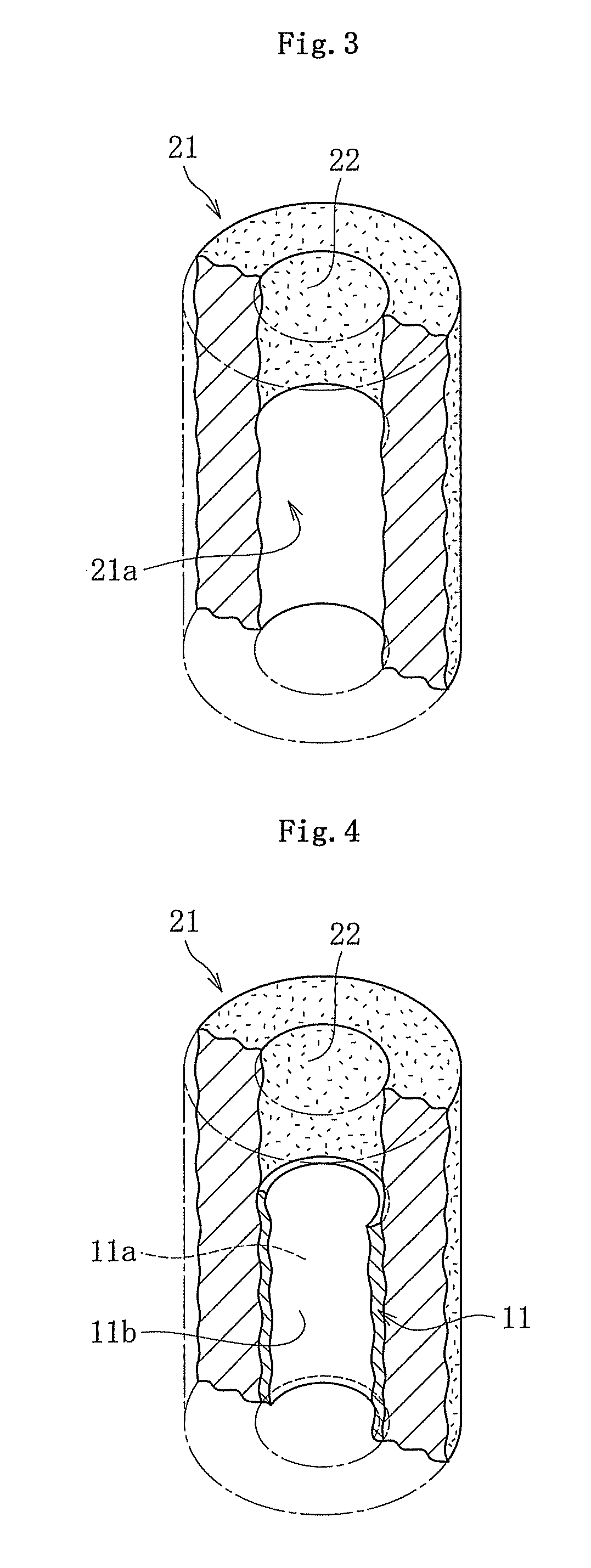
A fluid dynamic bearing device which can exhibit high bearing performance is provided at low costs by forming a highly accurate bearing gap.At least a region in the outer circumferential surface of a shaft 2 which faces the radial bearing gap is constituted of an electroformed part 11, and the region of the shaft 2 excluding the electroformed part 11 is constituted of a resin portion 12.

Description

TECHNICAL FIELD[0001]The present invention relates to a fluid dynamic bearing device.BACKGROUND ART[0002]Fluid dynamic bearing devices are for supporting a rotation-side component of a pair of components which relatively rotate by a film of a fluid occurring in the bearing gap. This type of bearing devices have the features such as high-speed rotation, high rotational accuracy and reduced noise, and are suitably used as bearing devices for motors mounted on various electrical machinery and apparatuses typically including information appliances, more specifically, as bearing devices for spindle motors in disk drives used in magnetic disk apparatuses such as HDD, optical disk apparatuses such as CD-ROM, CD-R / RW and DVD-ROM / RAM, magneto-optic disk apparatuses such as MD and MO, or as bearing devices for polygon scanner motors of laser beam printers (LBP), collar wheel motors of projectors, and bearing devices for motors such as fan motors.[0003]For example, in fluid dynamic bearing dev...

Claims


Application Information

Patent Timeline
IPC IPC(8): F16C32/06H02K7/08
CPCF16C17/02F16C33/14F16C17/107F16C2370/12F16C17/102H02K7/085F16C2220/82F16C2223/12F16C2223/14F16C2223/70F16C2226/14
Inventor HIBI, KENJIITO, KENJIYAMAMOTO, YASUHIRONIWA, HIROSHIKOMORI, ISAOYAMAMOTO, TETSUYA
Owner NTN CORP
Learn More