
Tactile sensor utilizing microcoils with spiral shape

Inactive Publication Date: 2009-02-19
TDK CORPARATION
View PDF2 Cites 12 Cited by
  • Summary
  • Abstract
  • Description
  • Claims
  • Application Information

AI Technical Summary

Benefits of technology

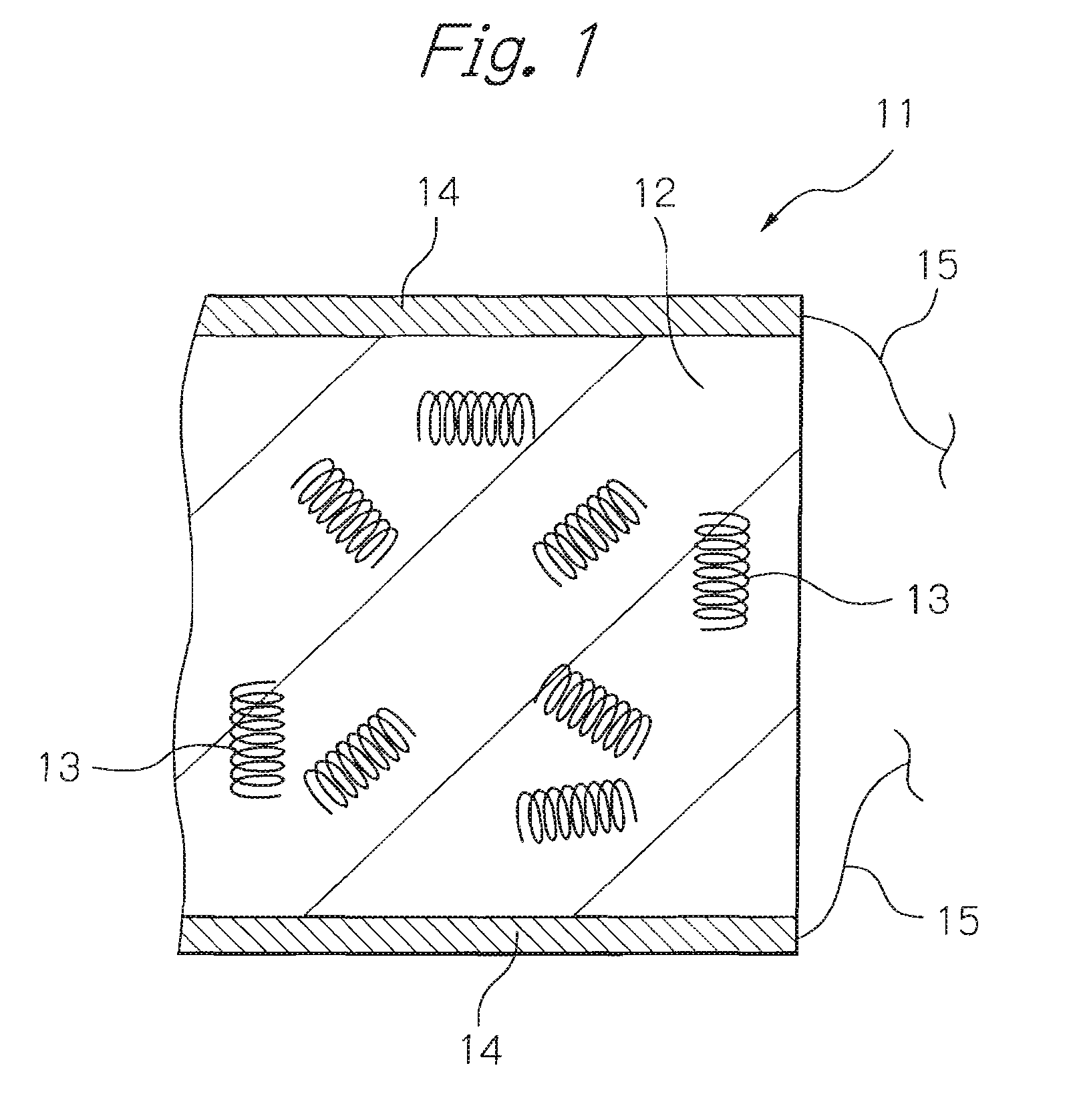
[0014]Therefore, an object of the present invention is to provide a material for tactile sensor, which is easy to be formed, and in which the shape, size and orientation of coils dispersed in the medium are sufficiently controlled; and is to provide a highly-sensitive tactile sensor with less variation in its characteristics even in the case of its miniaturization, manufactured by using the just-described material.
[0015]Further, another object of the present invention is to provide a manufacturing method of a material for tactile sensor, which is easy to be formed, and in which the shape, size and orientation of coils dispersed in the medium are sufficiently controlled.

Problems solved by technology

However, these sensors simply measure applied stress numerically, generally with low sensitivity, and are difficult to be miniaturized.
That is to say, the forming method cannot provide a controlled three-dimensional orientation of the CMCs in the resin.
Further, as the sensor is miniaturized toward the order of the coil length, an unintended deviation in the orientation of the CMCs inevitably occurs.
Such a deviation causes the variation in characteristics of the sensor, further may cause the decrease in sensitivity of the sensor in the case of its miniaturization.
However, the degree of the orientation has a certain limitation even if a magnetic field with fairly substantial intensity is applied to such a coil as the CMC.
Therefore, there are limits of desired uniformities of the shape and the size of the CMCs.
Even such non-uniform CMCs are not so easy to be produced.

Method used


Image

  • Tactile sensor utilizing microcoils with spiral shape
  • Tactile sensor utilizing microcoils with spiral shape
  • Tactile sensor utilizing microcoils with spiral shape

Examples


Embodiment Construction

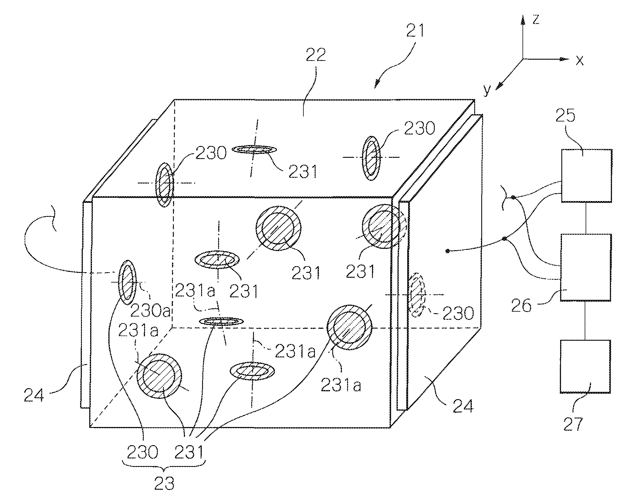
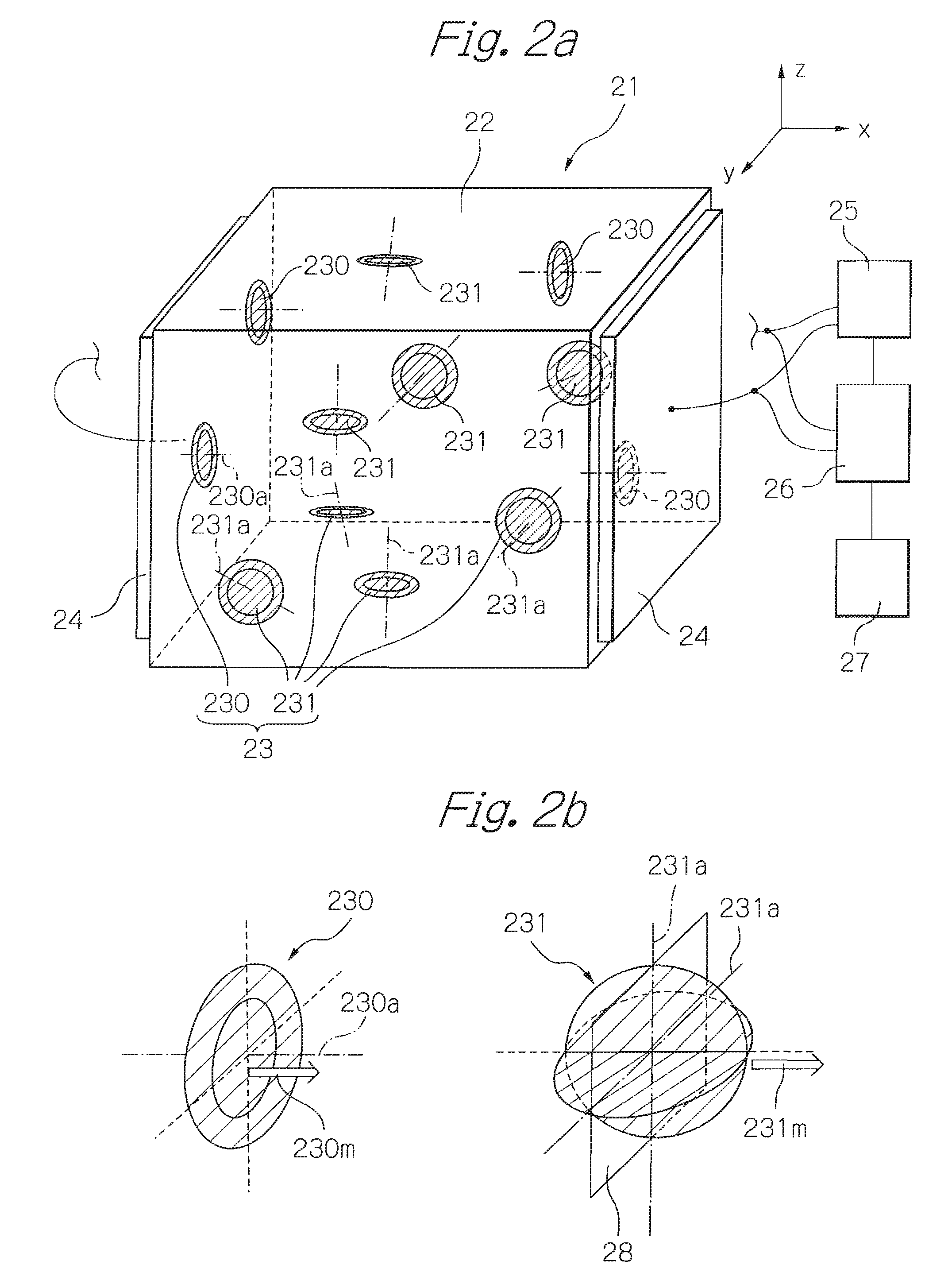
[0043]FIG. 2a shows a perspective view schematically illustrating the structure of one embodiment of the tactile sensor according to the present invention. And FIG. 2b shows schematic views for explaining the coil axis and the direction of magnetization in a micro coil. In these figures, x-, y-, and z-axis, which are orthogonal with one another, are defined in order to clarify directions.

[0044]As shown in FIG. 2a, a tactile sensor 21 includes: a medium 22 of rectangular solid; a plurality of micro coils 23 dispersed in the medium 22; and a pair of electrodes 24 provided respectively on both side surfaces opposed to each other along the x-axis of the medium 22. Here, the medium 22 with the dispersed micro coils 23 is considered as a tactile-sensitive material, or as a tactile-sense part formed of the material. In FIG. 2a, the number of the micro coils is extremely less than the real one, for viewability.

[0045]The medium 22 has certain elasticity, and certain conductivity lower than t...


PUM

PropertyMeasurementUnit
Ratioaaaaaaaaaa
Sensitivityaaaaaaaaaa
Magnetizationaaaaaaaaaa

Abstract

Provided is a material for tactile sensor, which is easy to be formed, and in which the shape, size and orientation of coils dispersed in the medium are sufficiently controlled. The tactile-sensitive material comprises a medium and a plurality of micro coils dispersed in the medium and constituting a LCR resonance circuit, and wherein each of the plurality of micro coils comprises at least one spiral coil portion, and coil axes of the plurality of micro coils are aligned along at least one direction and / or directed in at least one plane. When a tactile stress is applied to the tactile-sensitive material, the C component is varied significantly, which contributes to the improvement in sensitivity of the tactile sensor. Further, by providing a core at the coil center, the sensitivity is more improved.

Description

BACKGROUND OF THE INVENTION[0001]1. Field of the Invention[0002]The present invention relates to a material sensitive to tactile stress (a tactile-sensitive material) utilizing micro coils with a spiral shape, and further to a tactile sensor formed with the tactile-sensitive material. The present invention further relates to a manufacturing method of the tactile-sensitive material.[0003]2. Description of the Related Art[0004]A tactile sense, which is one of the five senses of human, is a sense to receive mechanical stimulations generated from the contact with outer objects; however being broadly interpreted, it includes a skin sensation such as pressure sense generated from the contact, tough feeling and so on.[0005]In recent years, many researches have been made to embody the tactile sense, which has a great deal of information, as artificial sensors. Such tactile sensors could be applied to various fields such as, for example, a robot having a skin sensation comparable with or exc...

Claims


Application Information

Patent Timeline
IPC IPC(8): G01L1/14H01F41/04
CPCH01F7/0294H01F17/0006H01F21/04H01F21/08Y10T29/4902H01F41/0273H01F41/046Y10T29/49002H01F41/0266
Inventor SHIMAZAWA, KOJI
Owner TDK CORPARATION
Learn More