
Screw driven mobile base

a mobile base and screw drive technology, applied in the direction of vehicles, transportation and packaging, etc., can solve the problems of turning friction beneath each wheel, complex control, gear and extra motor, etc., and achieve the effect of improving traction over rough or soft terrain, simple design, and minimal moving parts

Inactive Publication Date: 2009-02-19
LEXEN TIMOTHY CARL
View PDF2 Cites 17 Cited by
  • Summary
  • Abstract
  • Description
  • Claims
  • Application Information

AI Technical Summary

Benefits of technology

[0041]It is a further object of the invention to provide a mobile base that has redundant systems, so it can travel and maneuver even when some of its rotating elements are not working.
[0042]It is a further object of the invention to provide a mobile base that is simple in design, with a minimum of moving parts.
[0043]It is a further object of the invention to provide a mobile base that has improved traction over rough or soft terrain and improved obstacle climbing ability.
[0045]It is a further object of the invention to provide a mobile base that in some configurations has minimum suspension and low profile, so that that it can flip over and operate upside down.

Problems solved by technology

The problems which arise in using this kind of system outdoors are: the need for a sophisticated suspension; the complexity of controls, linkages, gears and extra motors; turning friction beneath each wheel; and the height of assembly needed, in that the vehicle is usually not compact in height.
These vehicles encounter problems in outdoor environments, such as dealing with dirt and uneven terrain, low obstacle climbing ability and overall complexity.
However, these screw driven vehicles do not possess true omni-directional / 3DEGREE OF FREEDOM capabilities.
These vehicles typically are heavy, with powerful engines required to overcome high friction.

Method used


Image

  • Screw driven mobile base
  • Screw driven mobile base
  • Screw driven mobile base

Examples


Embodiment Construction

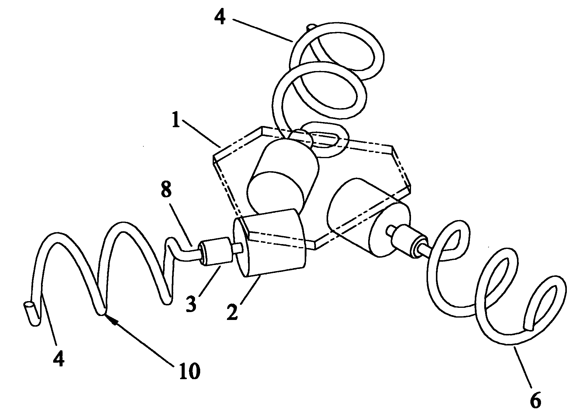
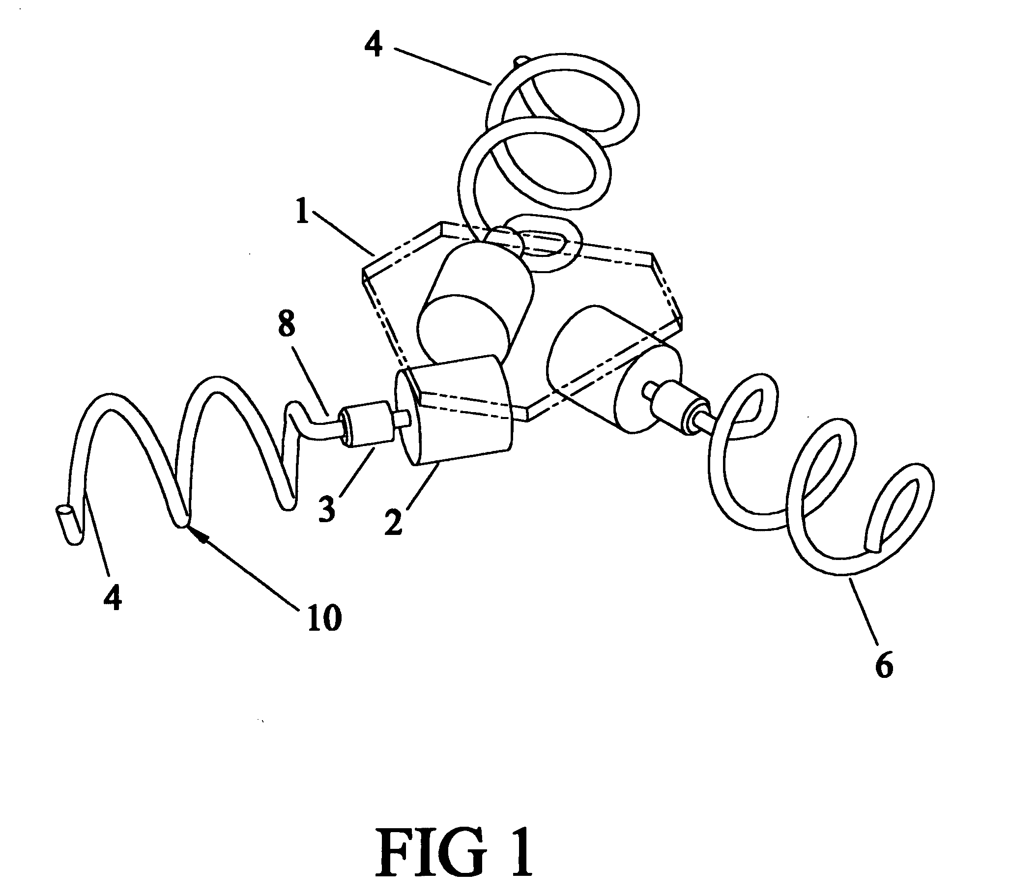
[0065]Referring to FIGS. 1-5, one embodiment of the device is shown. A central frame plate 1 supports three electric motors 2. The output shaft of each motor is connected by a coupling 3 to the central shaft 8 at one end of the drive screw 4.

[0066]The drive screw 4 consists of a helical coil shape of circular cross-section 12, with a central shaft 8 only where it connects to the coupling 3, with a hard, abrasion-resistant, low-friction (e.g., chrome) coating 9 on the spring material forming a outer helical edge profile 6 that normally contacts the ground surface. The helical coil shape 10 follows a cylindrical right hand helix of constant helix angle 15 relative to drive screw axis 7 (FIG. 2). The helical coil shape 10 and the coil cross-section 12 structurally support, and transmit motor torque to, the helical edge profile 6. At the end of each drive screw 4, the helix radius is preferably reduced so the end of the helix does not catch in the ground.

[0067]The frame plate 1 has the ...


PUM


Abstract

The present invention is a screw driven, mobile base for traversing a wide range of outdoor soft or rough surfaces and terrains. The device has three degrees of freedom in a plane and, thus, is highly maneuverable, able to travel in any horizontal direction relative to its orientation and able to orient itself independently of the direction of travel. Each screw comprises a structural core with an outer helical edge profile of curved cross-section, having an abrasion resistant, low friction material on the outer surface. The device rides on the low friction profiles and relies on the combined effects of the multiple drive screws against the ground surface. The drive screw axes are non-parallel in most of the configurations.

Description

CROSS-REFERENCE TO RELATED APPLICATIONS[0001]Not ApplicableSTATEMENT REGARDING FEDERALLY SPONSORED RESEARCH OR DEVELOPMENT[0002]Not applicableREFERENCE TO SEQUENCE LISTING, A TABLE, OR A COMPUTER PROGRAM LISTING COMPACT DISC APPENDIX[0003]Not applicableBACKGROUND OF THE INVENTION[0004]1. Field of the Invention[0005]The invention relates generally to a self propelled, all-terrain, omni-directional / 3DEGREE OF FREEDOM, highly maneuverable device for use on soft or rough ground surfaces.[0006]2. Background Information[0007]A three degree of freedom drive system on a robot or vehicle allows motion in any direction in a plane and rotation, independently, or together. Drive systems for three degree of freedom vehicles or rovers for outdoor use have used concepts from three categories summarized in the three paragraphs below.[0008]The drive system may use standard wheels, usually in the form of casters. Either the caster rotation is powered separately or, in another design, one or two wheel...

Claims


Application Information

Patent Timeline
IPC IPC(8): B62D57/036
CPCB62D57/036
Inventor LEXEN, TIMOTHY CARL
Owner LEXEN TIMOTHY CARL
Learn More