
Off-road engine configuration with noise reduction system

Inactive Publication Date: 2009-02-12
ARCTIC CAT
View PDF52 Cites 8 Cited by
  • Summary
  • Abstract
  • Description
  • Claims
  • Application Information

AI Technical Summary

Benefits of technology

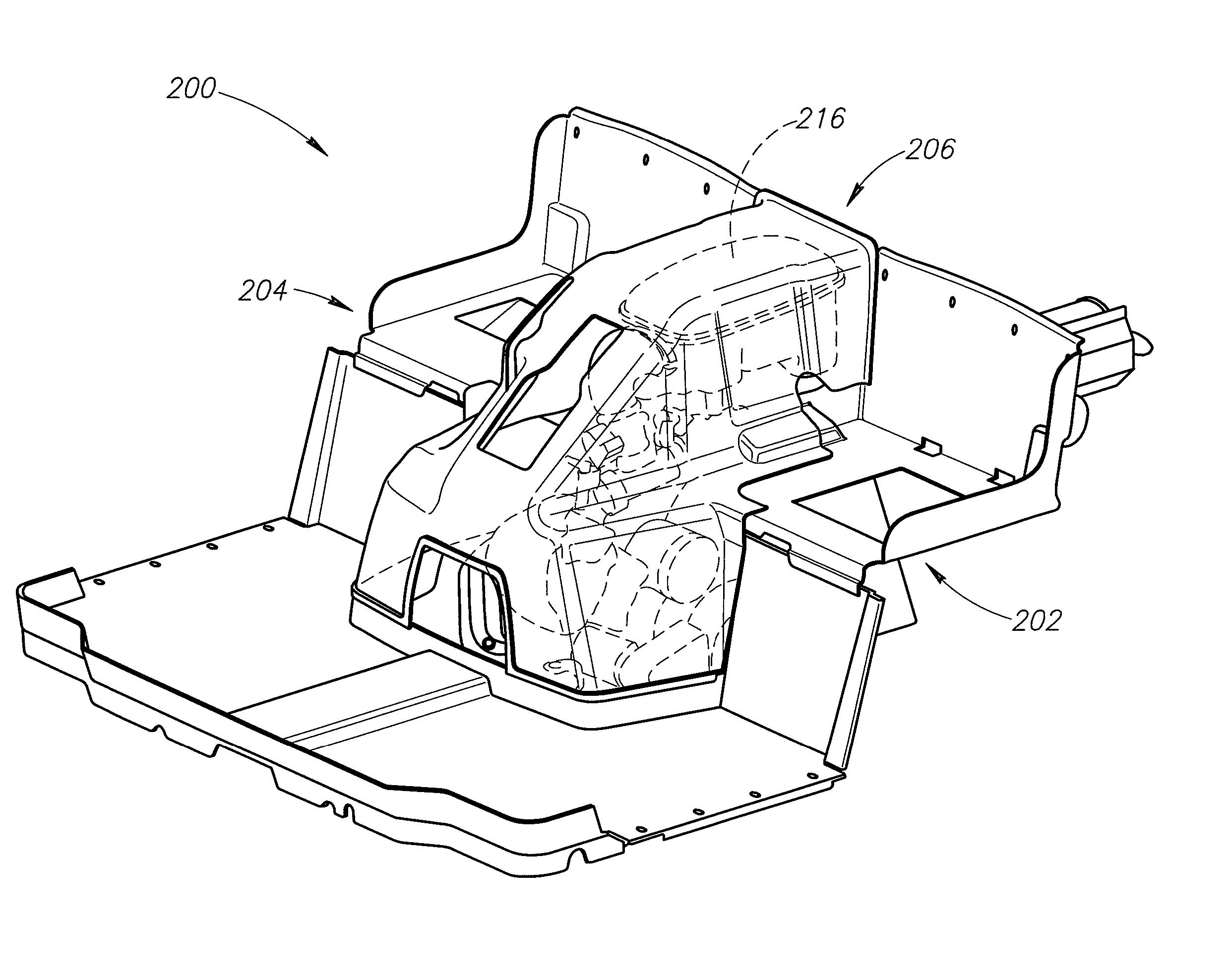
[0005]The present invention provides an engine and transmission arrangement for an off-road vehicle such as a RUV, UTV, or ATV that allows extra room for the driver and passenger and adds to vehicle rider comfort by reducing noise and heat levels. In one embodiment, a vehicle includes a frame, an engine, a transmission, and a driveshaft. The frame has a forward end and a rearward end. The engine is secured to the frame. The engine includes at least one cylinder and a crankcase generally below the cylinder. The transmission extends forward from the crankshaft in one preferred embodiment. The driveshaft is coupled to the transmission and to the drive or differential for driving the vehicle wheels. In addition, the vehicle includes an engine cover coupled to the frame and configured to substantially cover the cylinder and the crankcase while also configured to direct engine noise away from the engine (and operator and passenger(s)) and toward a rear portion of the vehicle. Moreover, the vehicle may include a sound shield and one or more splash panels located behind or otherwise adjacent the respective seating areas. The sound shield and the splash panels cooperate with the engine cover to direct the engine noise downward and rearward away from the seating areas, which in turn minimizes an amount of engine noise audibly detectable by the driver, passenger or both.
[0006]In one example, an off-road vehicle includes a frame having a forward end and a rearward end and a plurality of seating locations positioned generally side-by-side with respect to a transverse axis of the vehicle. The seating locations include a forward portion and a rearward portion. An engine is secured to the frame and includes a cylinder and a crankcase with a crankshaft positioned approximately beneath at least a portion of the cylinder. The cylinder includes a forward side and a rearward side. A transmission extends forward from the crankshaft and an air box is in fluid communication with the forward side of the cylinder and positioned above the engine. The engine may be substantially covered with an engine cover coupled to the frame and configured to substantially cover the cylinder, the crankcase, and the air box. The engine cover is further configured to direct engine noise from the engine toward a rear portion of the vehicle. A sound shield may be coupled to a rear portion of the engine cover and cooperates with the engine cover to direct the engine noise down and to the rear of the vehicle. The abutment between the shield and the cover is preferably sealed at the top to minimize an amount of engine noise that is audibly detectable to the driver and passenger(s).
[0007]In another example, a sound reduction system for an off-road vehicle includes an engine cover and a sound shield. The engine cover is coupled to a vehicle frame and configured to substantially cover an engine to direct engine noise away from the engine toward a rear portion of the vehicle. The sound shield is coupled to the frame and located between a seat tray and a cargo box of the vehicle. The sound shield cooperates with the seat tray to form a transversely extending passageway and further cooperates with the engine cover to minimize an amount of engine noise audibly detectable forward of the sound shield.

Problems solved by technology

However, some drawbacks with this conventional arrangement include a hot exhaust pipe; audible engine, transmission and drivetrain noise; and high engine running temperatures.
Spatial packaging issues may also occur with side-by-side seating arrangements because portions of the engine may take up space needed for the driver's legs, the passenger's legs, or both.

Method used


Image

  • Off-road engine configuration with noise reduction system
  • Off-road engine configuration with noise reduction system
  • Off-road engine configuration with noise reduction system

Examples


Embodiment Construction

[0019]The present invention generally relates to an off-road vehicle such as a multi-purpose vehicle (UTV), a recreational off-road vehicle (RUV), or all-terrain vehicle (ATV) with an engine, transmission and drivetrain advantageously configured to allow for extra room for the driver and passenger and the vehicle further includes an engine cover and backing member or shield configured to reduce engine, transmission and / or drivetrain noise the may be experienced by the driver, passenger, or both. In addition, the engine cover may operate as a thermal insulator to help reduce heat transfer from the engine as experienced by the driver, passenger, or both.

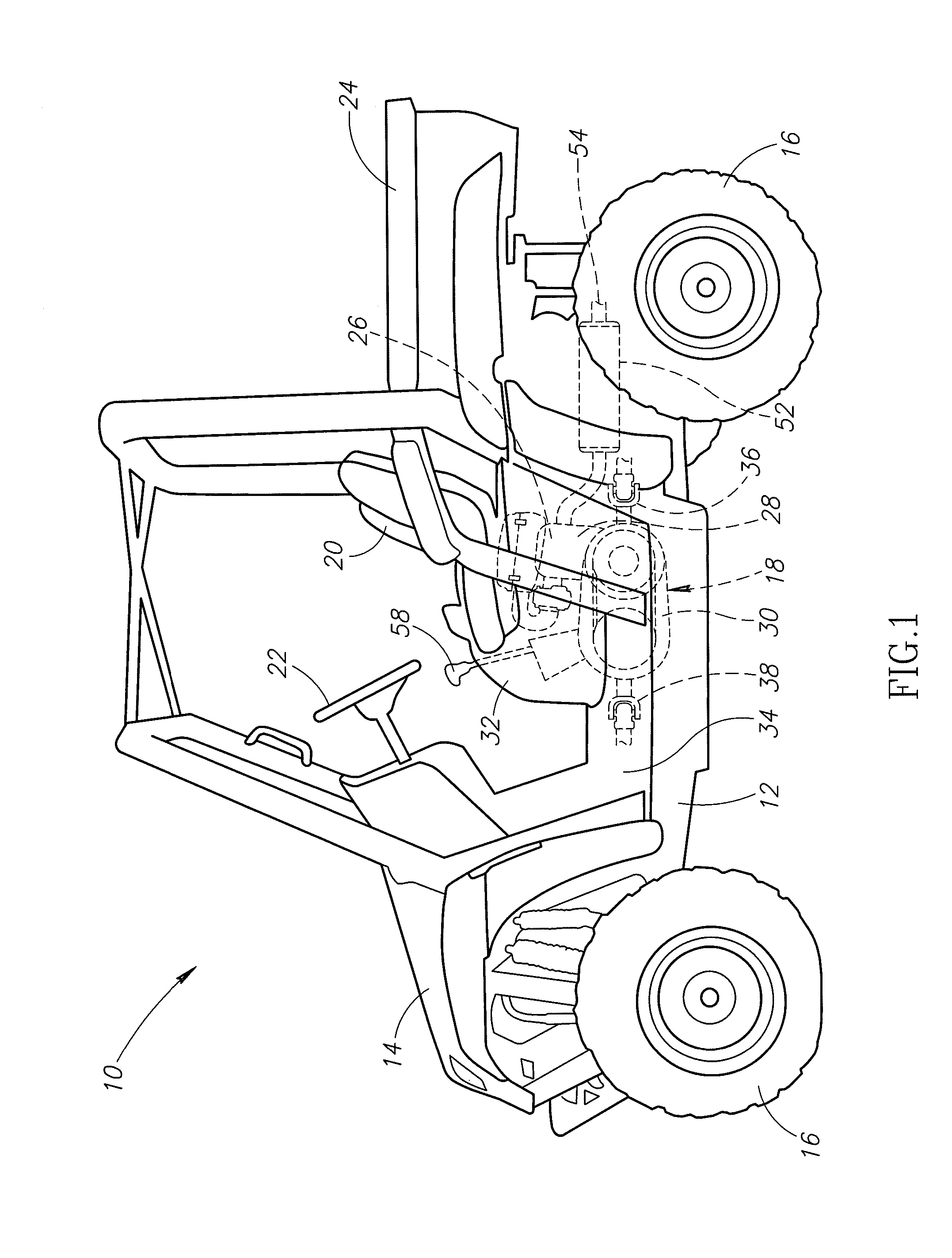
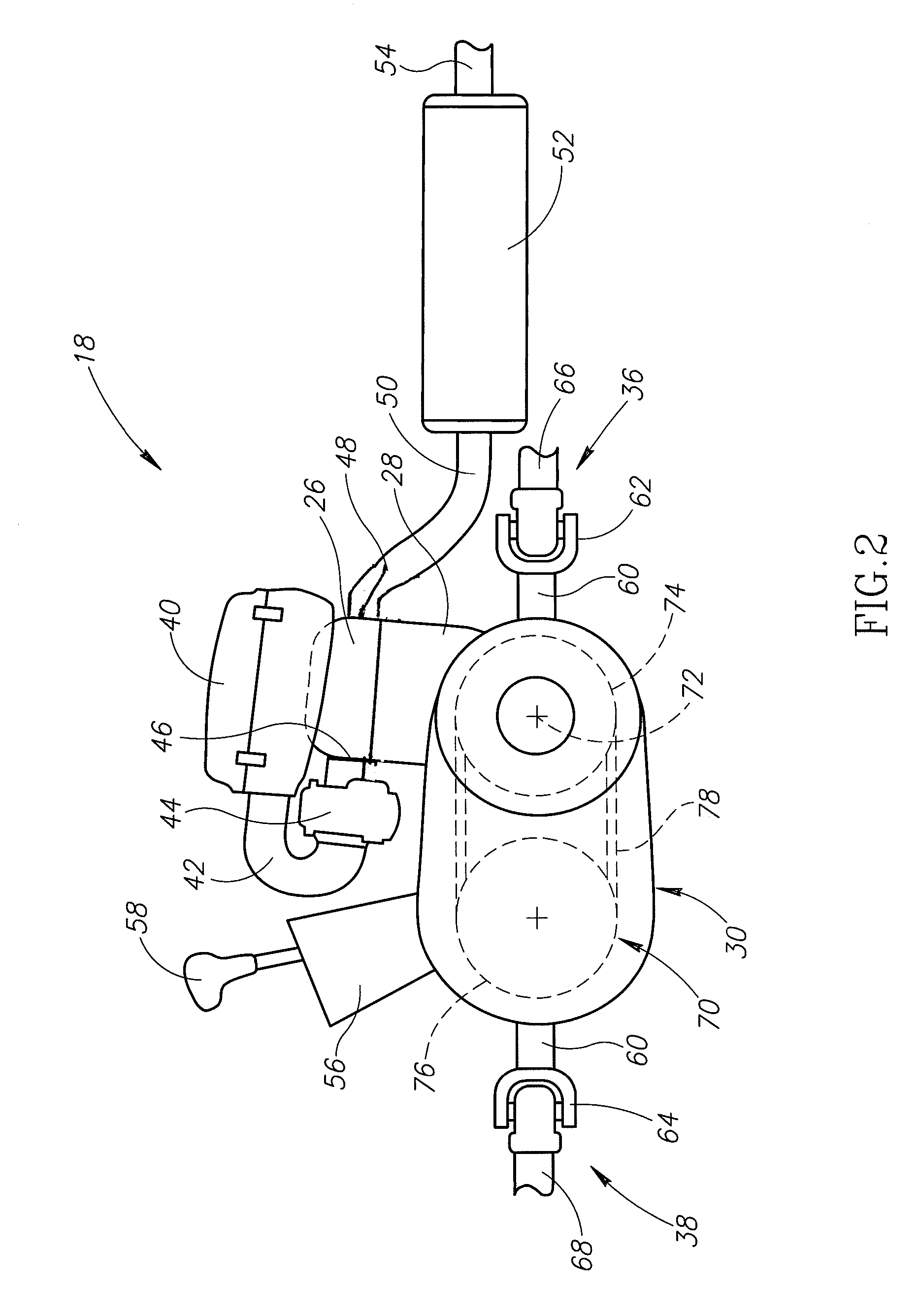
[0020]In one embodiment, the present invention provides an engine configuration for a vehicle 10 such as that illustrated in FIG. 1. Vehicle 10 includes a frame 12, a body 14, wheels 16, and an engine 18. The vehicle is arranged for side-by-side seating with individual bucket seats 20. Alternatively, a bench seat or other seating arran...


PUM


Abstract

An off-road vehicle for traveling over land includes a frame, an engine, a transmission, and a seating arrangement. The vehicle may include side-by-side or tandem seating positions. An engine cover is configured to substantially cover the engine and operate as a sound insulator to reduce engine noise from reaching an audible location relative to the seating positions. The engine cover may take the form of a console located between the seating positions and substantially covering the engine. Further, a backing member may be coupled to the engine cover to help channel engine noise toward the rear of the vehicle. The engine cover and the backing member may include, be made from, or be lined with an acoustic material.

Description

PRIORITY CLAIM[0001]This application constitutes a continuation-in-part of co-pending, commonly-owned U.S. patent application Ser. No. 11 / 129,069 filed May 12, 2005 entitled, “ALL-TERRAIN VEHICLE ENGINE CONFIGURATION.”FIELD OF THE INVENTION[0002]This invention relates generally to engine arrangements for off-road vehicles, such as all-terrain vehicles (ATVs) multi-purpose off-road (off-highway) utility vehicles (UTVs), and recreational off-highway vehicles (RUVs) and, more specifically, to an internal combustion engine noise suppression and directing arrangement.BACKGROUND OF THE INVENTION[0003]Standard ATV, UTV, and RUV engines are mounted to a frame at a position intermediate the front and rear wheels. The arrangement includes a crankcase and transmission below at least one cylinder. The transmission typically extends rearward from the crankcase. In the case of a continuously variable transmission, a drive pulley is coupled to the engine crank shaft. A belt extends rearward from t...

Claims


Application Information

Patent Timeline
IPC IPC(8): B60K5/00F02B77/13
CPCB60R13/083B62K5/01B60R13/0884B60R13/0838
Inventor MICHALKE, TIM W.KALSNES, KENNETH
Owner ARCTIC CAT
Learn More