
Laminate-cased battery formed with tab resin adhered to portions of tabs extended from laminate casing

a laminate-cased battery and tab resin technology, applied in the field of laminate-cased batteries, can solve the problems of difficult conventional laminate-cased batteries, and achieve the effect of high energy efficiency and high quality

Inactive Publication Date: 2009-02-05
SANYO ELECTRIC CO LTD
View PDF1 Cites 11 Cited by
  • Summary
  • Abstract
  • Description
  • Claims
  • Application Information

AI Technical Summary

Benefits of technology

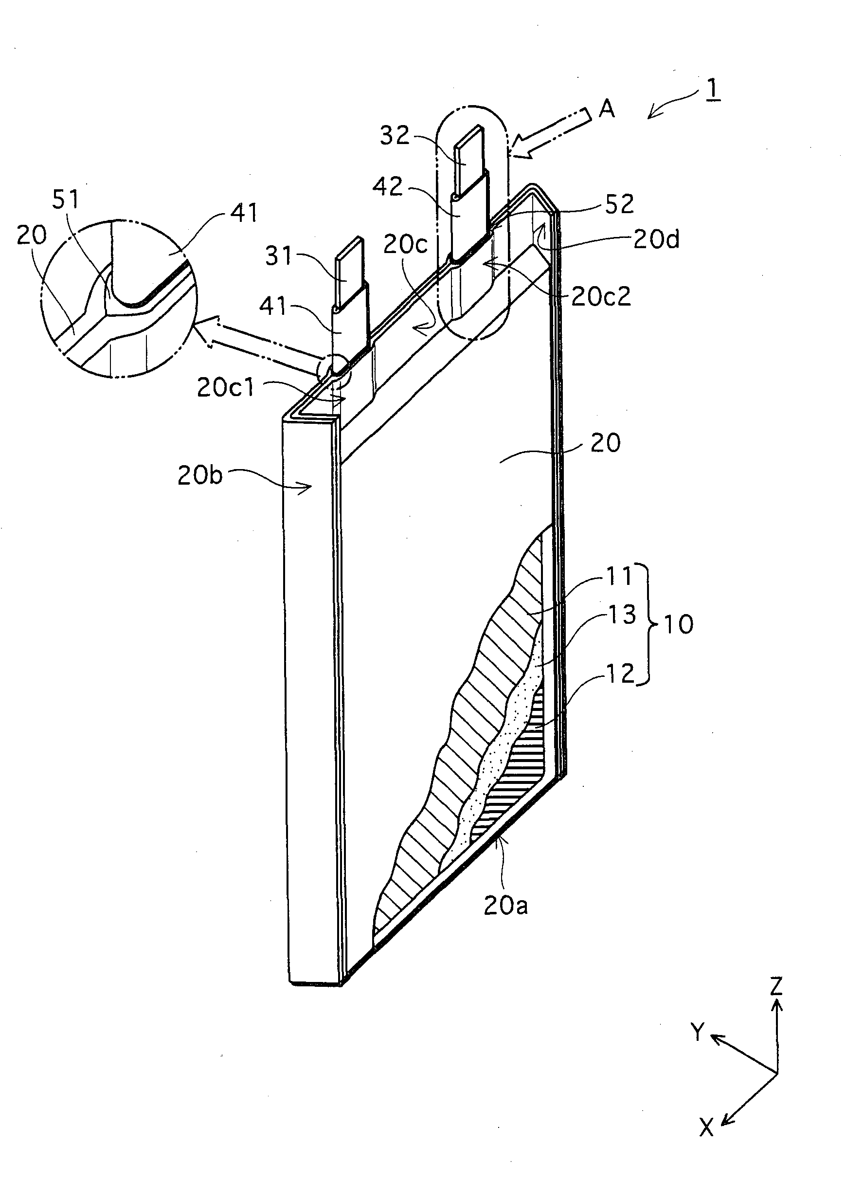
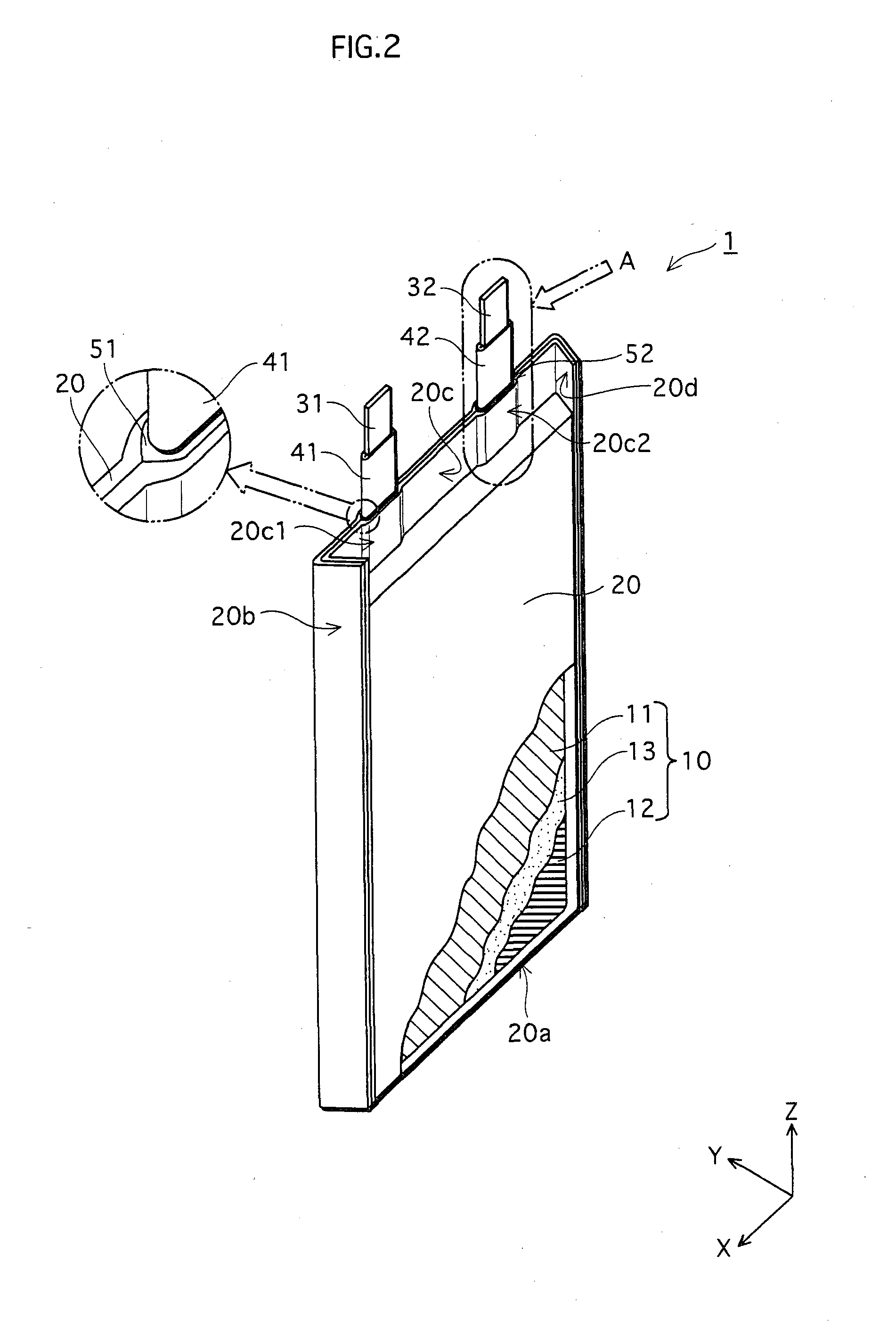
[0011]In view of the above-described problem, the object of the present invention is to provide a laminate-cased battery having a high quality and high energy efficiency, the tabs of which have been bent with a small curvature radius, while securely maintaining insulation between the metal layer of a laminate casing and the tabs when heat-sealing the outer edges of the laminate-cased battery.
[0013]As described above, the construction of a tab resin is different for each area in the laminate-cased battery according to the present invention. In other words, in the laminate-cased battery according to the present invention, a tab resin in the crossing area includes a high melting point resin layer. Therefore, the high melting point resin layer remains without fail even when heated during the heat sealing of the opening edge of the casing. This makes it possible to prevent a metal layer (aluminum (Al) layer or such) in a metal laminate sheet from being directly in contact with the positive and negative tabs.
[0018]Furthermore, it is not preferable to adopt the construction in which the tab resin in the crossing area includes only a low melting point resin layer, since this construction increases the risk of the metal layer of the metal laminate sheet making contact with the positive and negative tabs during the heat sealing.
[0022]Also, in the laminate-cased battery according to the present invention, a whole thickness of each of the tab resins in the respective extension areas may be thinner than a whole thickness of the tab resin in the crossing area. In this way, the bending rigidity of the tab resin in the extension area is improved by the difference in thickness as well as the different kinds of resin. In other words, the positive and negative tabs have been bent with a smaller curvature, thereby further improving energy efficiency.

Problems solved by technology

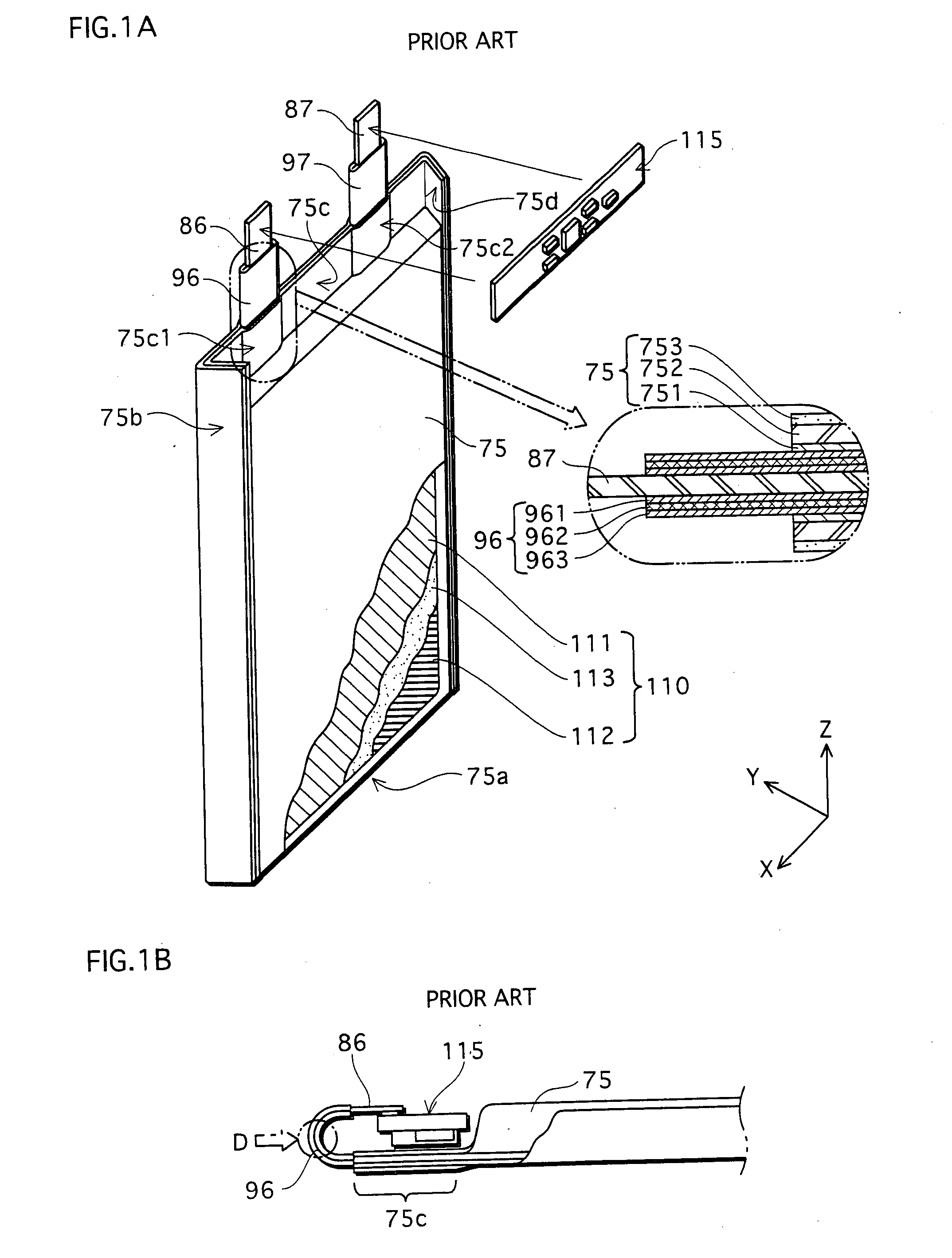
However, it is difficult for the conventional laminate-cased battery to further improve the energy efficiency by reducing a size of each of the bent portions of the positive and negative tabs 86 and 87.

Method used


Image

  • Laminate-cased battery formed with tab resin adhered to portions of tabs extended from laminate casing
  • Laminate-cased battery formed with tab resin adhered to portions of tabs extended from laminate casing
  • Laminate-cased battery formed with tab resin adhered to portions of tabs extended from laminate casing

Examples


example

[0073]The laminate-cased battery 1 according to the above-described embodiment is provided as an example. The following are the values of the tab resins 41, 42, 51, and 52.

[0074]Thickness of each of the sheet-shaped components 42a and 42b; 0.06 [mm]

[0075]Extension length of each of the inner tab resins 41 and 42 from the laminate casing 20; 2.0 [mm]

[0076]Thickness of each of the PEN layers 522 and 525 in the sheet-shaped components 52a and 52b; 0.015 [mm]

[0077](Comparison 1)

[0078]As shown in FIG. 6A, a laminate-cased battery according to a comparison 1 is different from the laminate-cased battery 1 according to the above-described embodiment, on the point that the sealed part tab resins 51 and 52 are not inserted. That is, in the laminate-cased battery according to the comparison 1, a tab resin 92 (sheet-shaped components 92a and 92b) having a single-layer structure with modified PP is adhered to a tab 82, and a PP layer 701 of a laminate casing 70 and a tab resin 92 are inserted be...


PUM


Abstract

In a laminate-cased battery, tab resins are adhered to positive and negative tabs, except outer ends of the tabs, and inserted (i) between a casing and the positive tab and (ii) between the casing and the negative tab in areas where the positive and negative tabs cross a heat-sealed edge of the casing.Each of the tab resins has (i) a crossing area in which the tab resin crosses the heat-sealed edge and (ii) an extension area in which the tab resin extends outward from the casing, in a direction in which the positive and negative tabs extend. Each crossing area includes a high melting point resin layer whose melting point is relatively higher than a melting point of each element that constitutes the extension areas.

Description

BACKGROUND OF THE INVENTION[0001](1) Field of the Invention[0002]The present invention relates to a laminate-cased battery, and in particular to the construction of tab resins adhered to tabs.[0003](2) Description of the Related Art[0004]Laminate-cased batteries have been prevalent with the widespread use of mobile apparatuses, such as mobile phones. The following describes the construction of a laminate-cased battery, with reference to FIGS. 1A and 1B.[0005]As shown in FIG. 1A, a laminate-cased battery has the construction in which an electrode assembly 110 is housed in a laminate casing 75 that is formed with a metal laminate sheet. The electrode assembly 110 is composed of a positive plate 111, a negative plate 112, and a separator 113. The laminate casing 75 is formed by pressing and bending one metal laminate sheet into a bag-shape, and heat-sealing three outer edges 75b, 75c, and 75d that are open. The bent portion of the metal laminate sheet is a bottom portion 75a of the lam...

Claims


Application Information

Patent Timeline
IPC IPC(8): H01M2/02H01M50/103H01M50/105H01M50/183H01M50/531H01M50/55H01M50/553
CPCH01M2/0207H01M2/021H01M2/26H01M2/08H01M2/0287Y02E60/10H01M50/124H01M50/183H01M50/531H01M50/105H01M50/55H01M50/103H01M50/553
Inventor KODAMA, YASUNOBU
Owner SANYO ELECTRIC CO LTD
Learn More