
Biogas Producing Facility With Anaerobic Hydrolysis

a technology of anaerobic hydrolysis and biogas, which is applied in the direction of biochemical equipment, water cleaning, biochemical equipment and processes, etc., can solve the problems of high operational cost of additives, unfavorable economic development, and high cost of additives, so as to achieve hydrolysis of digested organic waste, economic development, and the effect of increasing the yield of biogas

Inactive Publication Date: 2009-02-05
BIO CIRCUIT
View PDF5 Cites 15 Cited by
  • Summary
  • Abstract
  • Description
  • Claims
  • Application Information

AI Technical Summary

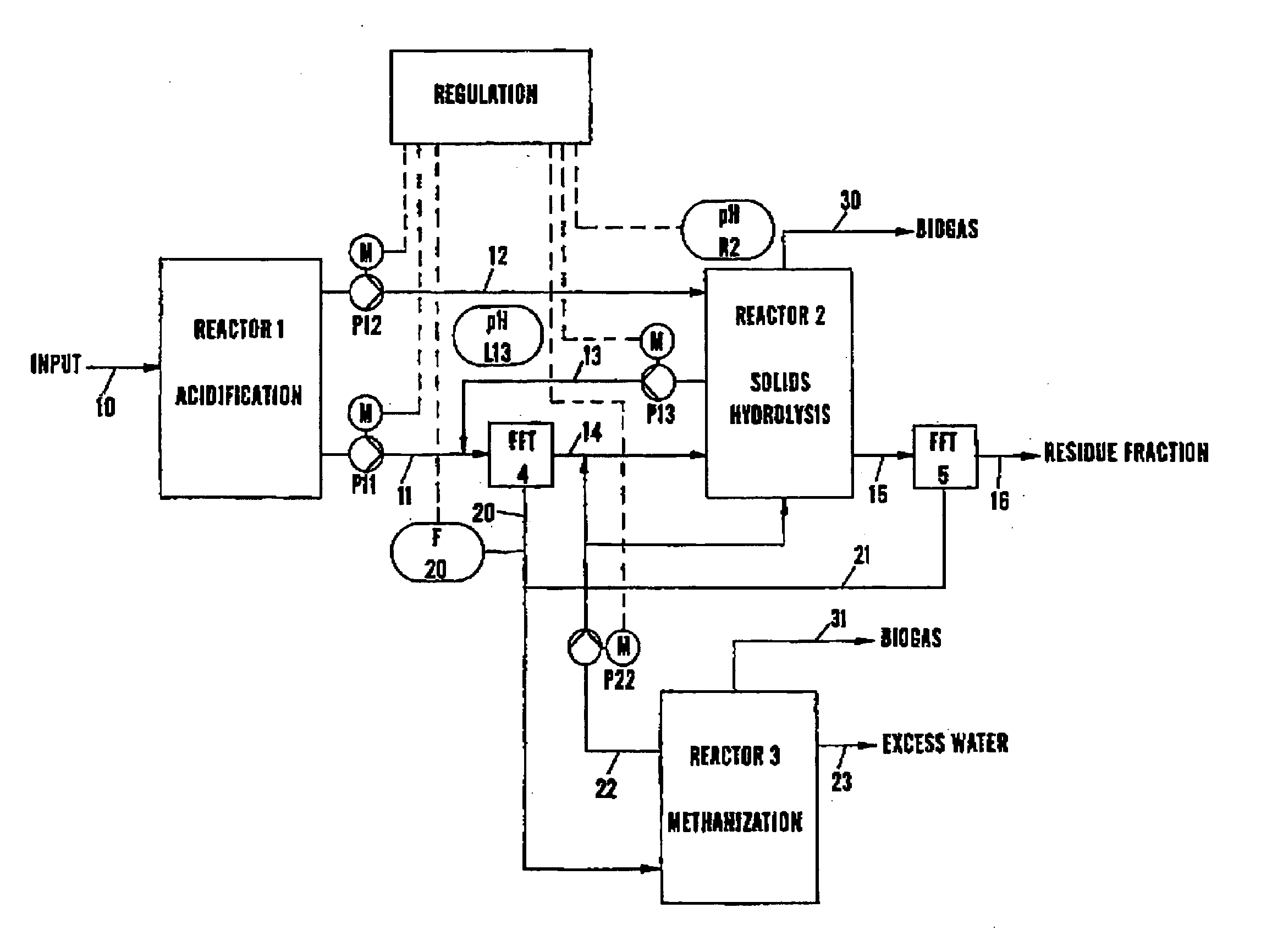
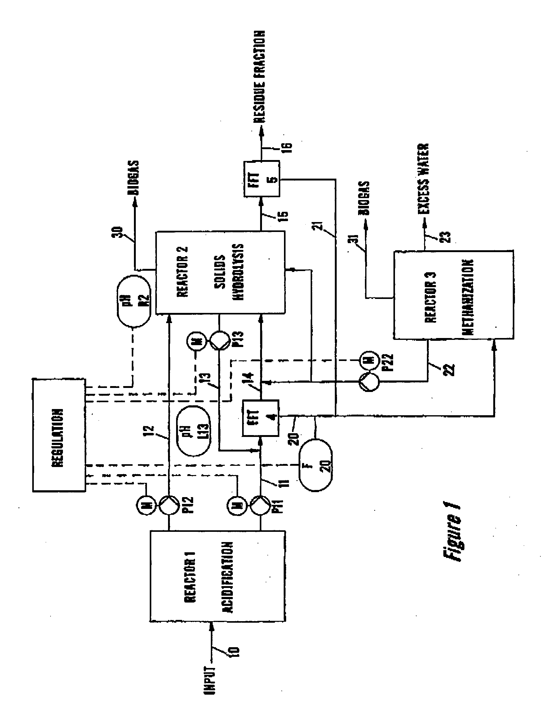
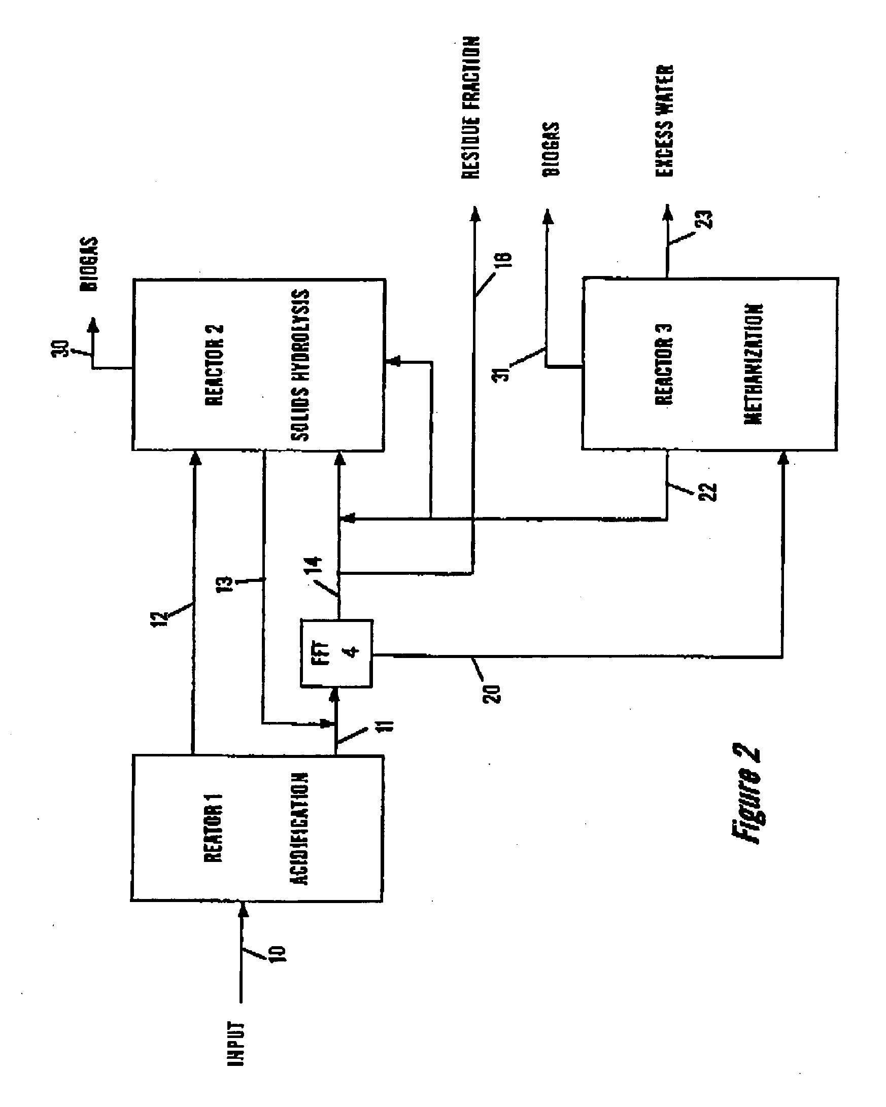
Benefits of technology

[0007]It is an advantage of the present invention that a method and a system for conversion of organic waste into biogas is provided with an increased yield of biogas, without the addition of chemicals, enzymes or water, hereby providing an economically more feasible production of biogas.
[0008]Thus, according to the present invention, a method of producing biogas from organic waste is provided, comprising the consecutive steps of:
[0009]i) digestion of the organic waste in a first reactor;
[0010]ii) hydrolysis of the digested organic waste in an anaerobic hydrolysis tank; and
[0011]iii) digestion of the hydrolyzed organic waste in a second reactor;wherein evolved gases are removed from the anaerobic hydrolysis tank.
[0012]In one aspect of the present invention the above-mentioned method may be performed in a biogas producing facility comprising a first reactor for holding organic waste for production of biogas by digestion and having an output for digested waste, and an anaerobic tank that is connected to the reactor output for anaerobic hydrolysis of the digested waste, and having an output for hydrolysed material that is connected to an input of a second reactor for adding hydrolyzed material to the content of the reactor and wherein a gas is passed through the headspace of the anaerobic hydrolysis tank for removal of gases from the digested waste.

Problems solved by technology

There is a high demand for industrial waste for this purpose, which has made it a rather expensive and limited resource.
Systems requiring addition of enzymes and / or chemicals has been developed, but suffers from high operational costs from the additives, hereby being economically unfavourable.
Although, digestion of excess wastewater sludge reduces the amount of final dewatered sludge, the final disposal of the sludge still has high costs.
Also, many wastewater treatment plants have insufficient organic matter for de-nitrification.

Method used


Image

  • Biogas Producing Facility With Anaerobic Hydrolysis
  • Biogas Producing Facility With Anaerobic Hydrolysis
  • Biogas Producing Facility With Anaerobic Hydrolysis

Examples


example 1

Increased Biogas Production from Semi Liquid Manure by Removal of Evolved Gases

[0057]Experiments have been performed on semi liquid manure to investigate the effect of a hydrolysis tank with a communication between the headspace of the anaerobic hydrolysis tank and a biogas outlet from a reactor, compared to a conventional closed hydrolysis tank.

[0058]After the first digestion of the material, three experiments (A, B and C) were performed; the total biogas productions after the subsequent digestion steps are given below:

Biogas produced in m3 / 1000 KgConditionsdry matter supplied.A) control experiment, no hydrolysis;26,B) hydrolysis in a closed hydrolysis72, (176% increase comparedtank;to experiment A)C) hydrolysis in a hydrolysis tank with107, (311% increase compareda communication between theto experiment A)headspace and a biogas outlet(49% increase comparedfrom a reactor.to experiment B)

[0059]It is noted that the removal of gases from the hydrolysis tank (C) has a surprisingly high...

example 2

Increased Biogas Production from Sludge by Removal of Evolved Gases

[0060]Experiments have been performed on sludge from a sewage treatment plant, with respect to temperature of gas and hydrolysis time, to investigate the effect on the total biogas production. Experiments were performed with either atmospheric air with ambient temperature or with heated atmospheric air passing through the headspace of the hydrolysis tank.

[0061]After the first digestion of the sludge, four experiments (A control, B, C, and D) were performed; B, C and D where each repeated five times as addition experiments, the total biogas productions after the subsequent digestion steps are given below:

Biogas produced% Increasein m3 / 1000 Kg dryMean,comparedConditionsmatter supplied.m3to exp. A)A) control experiment, no67————67—hydrolysis;B) 4 hours hydrolysis,567284821037918%atmospheric air, ambienttemperature;C) 18 hours hydrolysis,7088991041099440%atmosphericair, ambient temperature;D) 8 hours hydrolysis,120127131...

example 3

Increased Biogas Production from a Mixture of Semi Liquid Manure and Industrial Waste by Removal of Evolved Gases

[0063]As it was seen in example 1, the removal of gases from the headspace by a communication between the headspace of the anaerobic hydrolysis tank and a biogas outlet from a reactor gave an increased yield. Experiments have furthermore been performed on a mixture of semi liquid manure and industrial waste, with regard to the influence of hydrolysis time and the time range wherein the communication between the headspace and a biogas outlet is provided.

[0064]After the first digestion of the material, four experiments (A, B, C and D) were performed; the total biogas productions after the subsequent digestion steps are given below:

Biogas produced in m3 / 1000 KgConditionsdry matter supplied.A) control experiment, no hydrolysis;153,B) 2 hours hydrolysis in a hydrolysis164, (7% increase comparedtank with a communication between theto experiment A)headspace and a biogas outlet f...


PUM

PropertyMeasurementUnit
temperatureaaaaaaaaaa

Abstract

The present invention relates to a method and a facility for conversion of organic waste into biogas, i.e. a methane containing gas, with an improved efficiency and economy. The method comprises three consecutive steps of: i) digestion of the organic waste in a first reactor; ii) hydrolysis of the digested organic waste in an anaerobic hydrolysis tank; and iii) digestion of the hydrolyzed organic waste in a second reactor; wherein evolved gases are removed from the anaerobic hydrolysis tank. The biogas producing facility comprises a first reactor for holding organic waste for production of biogas by digestion and having an output for digested waste, and an anaerobic tank that is connected to the reactor output for anaerobic hydrolysis of the digested waste and having an output for hydrolysed material that is connected to an input of a second reactor for adding hydrolysed material to the content of the reactor and wherein a gas is passed through the headspace of the anaerobic hydrolysis tank for removal of gases from the digested waste. The anaerobic hydrolysis process and the evaporation and wash out of gases from the hydrolysis tank makes the energy content of material that has not been digested in the reactor easier and immediate available for bacterial digestion and the evaporation and wash out of gases in the hydrolysis tank further reduce inhibition of the bacteria and enhance the biogas production velocity and thus, the hydrolysed material is fed back into a reactor for further bacterial conversion into biogas. Furthermore, the gas that has been passed through the headspace of the anaerobic hydrolysis tank may be cooled in a heat exchanger so that the condensable gases of the gases removed from the anaerobic hydrolysis tank content condense, the condensed water containing the removed gases.

Description

FIELD OF THE INVENTION[0001]The present invention relates to a method and a system for conversion of organic waste into biogas, i.e. a methane containing gas, with an improved efficiency and economy.BACKGROUND OF THE INVENTION[0002]Typically, today's biogas producing facilities depend on supply of industrial waste containing fat to be economically feasible. Fat has a high energy to weight ratio, which makes it a useful input for biogas producing facilities. There is a high demand for industrial waste for this purpose, which has made it a rather expensive and limited resource. Thus, there is a need for a biogas producing facility that makes it possible to substitute industrial waste with other materials, e.g. other low-energy waste materials.[0003]Conventionally, organic material from e.g. wastewater plants and livestock dung is processed in simple systems. Systems requiring addition of enzymes and / or chemicals has been developed, but suffers from high operational costs from the addi...

Claims


Application Information

Patent Timeline
Patent Type & Authority Applications(United States)
IPC IPC(8): C02F11/04
CPCC02F11/04C12M21/04Y02E50/343C12M23/58C12M47/06C12M23/36Y02E50/30Y02W10/20
Inventor JENSEN, JANJENSEN, PREBEN
Owner BIO CIRCUIT
Learn More