
Electron beam enhanced nitriding system

a nitriding system and electron beam technology, applied in the field of nitriding systems, can solve the problems of high strength-to-weight ratio, many engineering materials exhibit undesirable property changes, and materials typically exhibit high wear rates, and achieve the effect of easy scaling

Inactive Publication Date: 2009-02-05
NAVY U S A AS REPRESENTED BY THE THE SEC OF THE
View PDF2 Cites 5 Cited by
  • Summary
  • Abstract
  • Description
  • Claims
  • Application Information

AI Technical Summary

Benefits of technology

"The present invention provides a system for nitriding materials using plasmas produced by high-energy electron beams. This system offers improved efficiency and uniformity compared to conventional sources. The high-energy electron beams create a low electron temperature plasma with a high concentration of atomic ions and radicals, which are important for promoting high nitride layer growth rates. The system can be scaled to large areas and can be used to treat difficult geometries. The unique properties of electron beam-generated plasmas make this system ideal for plasma nitriding."

Problems solved by technology

Aluminum alloys possess high strength-to-weight ratios; however, these materials typically exhibit high wear rates in high friction or high force environments, which can be decreased by nitriding.
However, many engineering materials exhibit undesirable property changes, such as loss of corrosion resistance or overtempering below the temperatures necessary to get useful nitrided layers in an acceptable period of time with respect to typical product manufacturing times (i.e., less than tens of hours).
However, there are difficulties associated with this technique.
Temperature control at the material surface is difficult to achieve as the current necessary to sustain the discharge results in unpredictable resistive heating of the nitrided material.
Furthermore, nitriding of large areas is often desirable, but may be limited by the output of the system power supplies because large currents are necessary to drive large areas to typical discharge voltages (500-1000 Volts).
Additionally, the applied negative voltage, while necessary to sustain the glow discharge, will result in positive ion energies that may be different from the most effective ion energy for nitriding.
In conventional sources, gas ionization and dissociation favors the species with the lowest ionization and dissociation energies, and thus these sources provide little control over the relative concentrations of plasma species.

Method used


Image

  • Electron beam enhanced nitriding system
  • Electron beam enhanced nitriding system
  • Electron beam enhanced nitriding system

Examples


Embodiment Construction

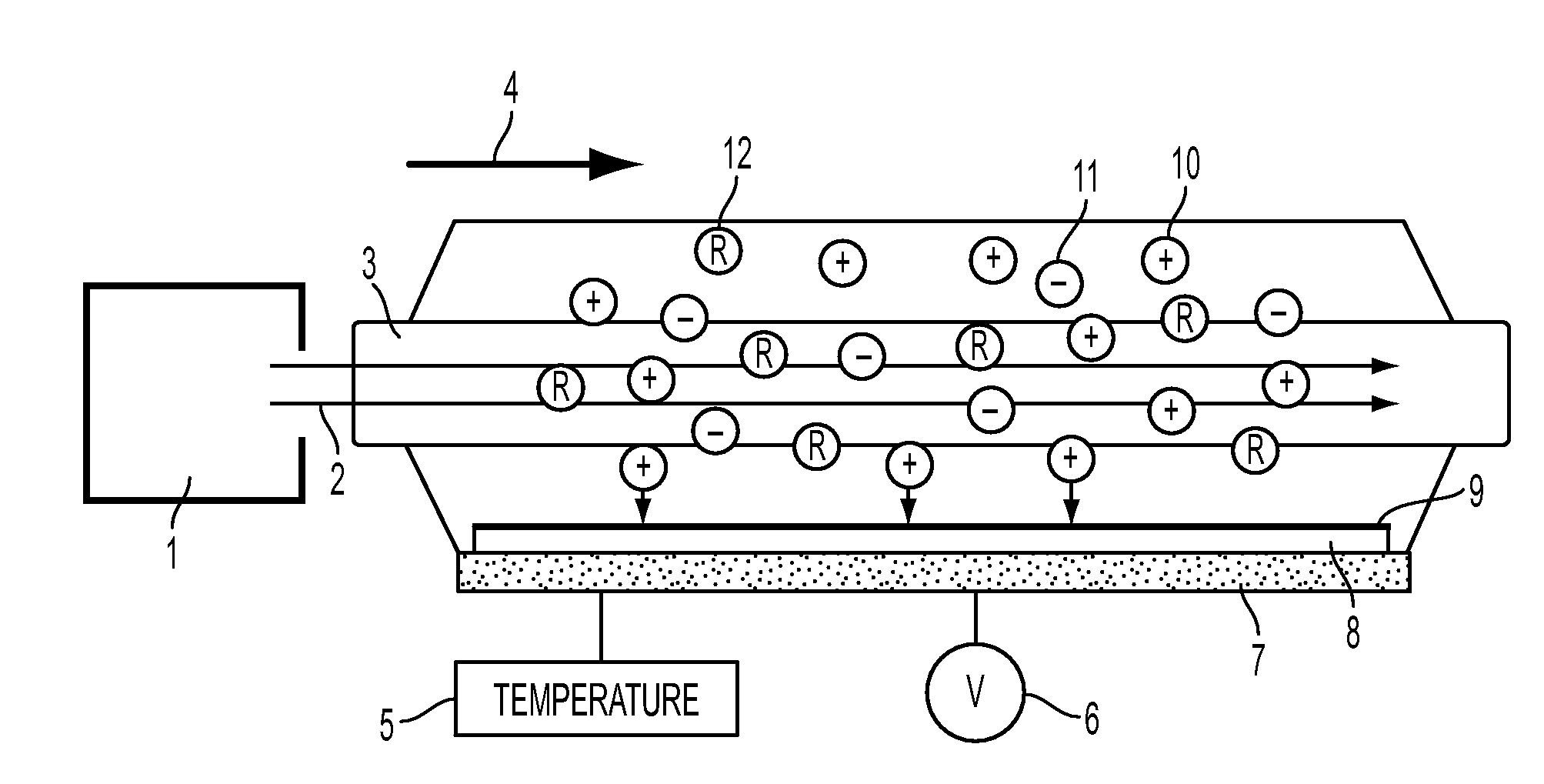
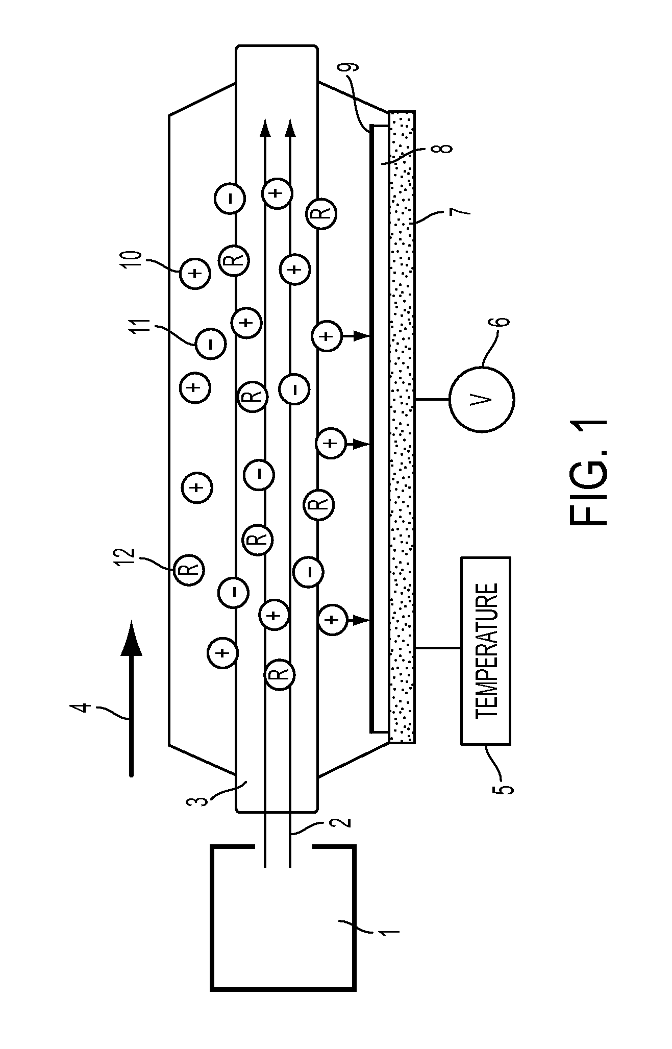
[0020]A preferred embodiment of the Electron Beam Enhanced Nitriding System (EBENS) of the present invention as shown in FIG. 1 includes a beam source 1, an electron beam 2, a beam-generated plasma 3, a direction of external magnetic field 4, a temperature control 5, a bias voltage 6, a conducting electrode 7, a substrate 8, a nitride layer 9, a positive ion 10, an electron 11, and a neutral radical 12. EBENS uses a multi-kilovolt (2-5 kV) sheet electron beam that is injected into a nitrogen-based background. The beam is magnetically confined and efficiently ionizes and dissociates the background gas. The beam width (into page) is variable and can exceed a meter. The thickness is up to a few centimeters and is maintained over the beam length by an axial magnetic field that exceeds 100 Gauss. The length of the plasma sheet is determined by the range of the electron beam, which scales roughly as the beam energy squared divided by the gas pressure (E2 / P). The range is usually maintaine...


PUM

PropertyMeasurementUnit
depthaaaaaaaaaa
discharge voltagesaaaaaaaaaa
areaaaaaaaaaaa

Abstract

An electron beam enhanced nitriding system that passes a high-energy electron beam through nitrogen gas to form a low electron temperature plasma capable of delivering nitrogen ions and radicals to a substrate to be nitrided. The substrate can be mounted on an electrode, and the substrate can be biased and heated.

Description

BACKGROUND[0001]1. Field of the Invention[0002]The present invention relates to nitriding systems and, more specifically, to a system for nitriding materials using plasmas produced by high-energy electron beams.[0003]2. Description of the Related Art[0004]Nitriding generally refers to a process designed to increase the concentration of nitrogen at the surface of a material. The depth to which the incorporated nitrogen extends varies but is typically 1 to 10 microns. Nitriding processes are currently employed to improve the hardness and wear resistance of materials with otherwise attractive engineering properties. Corrosion resistant stainless steel for example is a relatively soft material that can be nitrided to increase the surface hardness. Aluminum alloys possess high strength-to-weight ratios; however, these materials typically exhibit high wear rates in high friction or high force environments, which can be decreased by nitriding.[0005]Nitriding is a treatment process for mate...

Claims


Application Information

Patent Timeline
Patent Type & Authority Applications(United States)
IPC IPC(8): C23C8/36C23C16/513C23C8/24H01J37/32H05H1/20H05H1/24
CPCC23C8/36H01J37/32009H05H1/24H01J2237/3387H01J37/3233H05H1/26H05H2245/40
Inventor WALTON, SCOTT GLEONHARDT, DARRINMEGER, ROBERT A.FERNSLER, RICHARD F.MURATORE, CHRISTOPHER
Owner NAVY U S A AS REPRESENTED BY THE THE SEC OF THE
Learn More