Position control method, position control device and electric device including the position control device

a technology of position control and control device, which is applied in the direction of pulse position modulation, pulse technique, dynamo-electric converter control, etc., can solve the problems of reducing the precision of machining, the inability to accurately control the position, so as to ensure the precision and the immediateness of the position change, ensure the precision and the effect of the position chang

Inactive Publication Date: 2009-01-29
POSITEC POWER TOOLS (SUZHOU) CO LTD
View PDF8 Cites 2 Cited by
  • Summary
  • Abstract
  • Description
  • Claims
  • Application Information

AI Technical Summary

Benefits of technology

[0006]An objective of the present invention is to provide a position control method, which is simple and practicable.
[0008]A further objective of the present invention is to provide a position control device that is of low manufacturing costs and excellent operability.
[0009]A further objective of the present invention is to provide a position control device which is suitable for applications the non-digital control field and provides high precision.
[0010]Yet a further objective of the present invention is to provide an electric device that realizes position control in a convenient and precise manner.
[0014]The effectiveness of the technique solution in accordance with the present invention is that since the present invention provides an open-loop control method, the direction and speed of position change is completely controlled by an operator and thus the immediateness of position change is ensured; the control solution employs a pulse generator 11 and the common motor 13, which make the manufacturing cost low and benefit popularization and applications; the coupling circuit 12 is simply an electric circuit and thus, the performing unit 20 can rapidly respond to an input from the pulse generator 10; and the use of an H-bridge circuit ensures the performance of starting and braking function of the common motor 13. Conclusively, the position control method, the position control device and the electric device including the position control device in accordance with the present invention sufficiently ensure the precision and the immediateness of position change.

Problems solved by technology

However, besides inconvenience of operation and being time- and effort-consuming, such a manual operation of the supporting arm is imprecise, leading to imprecise position control and reduction of machining precision.
However, using the server motor to realize precise position control makes the manufacturing costs very high, and is particularly detrimental to applications and polarization in the field of non-digital control.

Method used


Image

  • Position control method, position control device and electric device including the position control device
  • Position control method, position control device and electric device including the position control device
  • Position control method, position control device and electric device including the position control device

Examples


Embodiment Construction

[0022]In the following, the present invention will be described in details with respect to a preferred embodiment thereof, reference being had to the attached drawings.

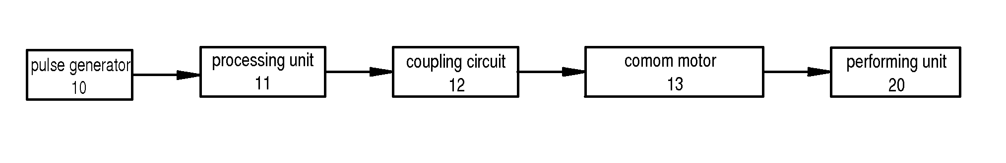
[0023]An attempt of the present invention is to use a common motor 13 to perform precision open-loop control of position change and replacing control systems based on servo motors or step motors, which are of high costs. The position change may include changes of angle and displacement and is commonly applicable to position change in the field of mechanical or electro-mechanical tools. In the preferred embodiment of the present invention, the present invention is described with reference to the swinging operation of a supporting arm 3 of a miter saw of power tools. However, those having ordinary skills in the art may contemplate various other applications, such as position change of a cutter frame or wheel of a lawn mower in order to effect cutting of grass at different heights.

[0024]The common motor 13 employed in th...


PUM


Abstract

A position control method, a position control device and an electric device and an electric device including the position control device are provided. The position control device includes a common motor (13), a performing unit (20) coupled to the motor to perform position change, a pulse generator (10) generating alterable pulse signals, a process unit (11) continuously collecting and processing the pulse signals and generating pulse width modulated signals, a coupling circuit (12) which connects the processing unit and the common motor and sends the pulse width modulated signals to the motor, the common motor receiving and performing the pulse width modulated signals and driving the performing unit to change its position. The position control device can perform real time open-loop control of position change.

Description

BACKGROUND OF THE INVENTION[0001]1. Field of the Invention[0002]The present invention relates generally to a position control method, a control device and an electric device including the device, and more particularly, to an open-loop position control method, which uses a common motor to realize stepping and successive position change, and a control device and an electric device including the device.[0003]2. The Related Arts[0004]In many applications, position change of a moving part needs a relatively fast motion and a relatively slow motion to satisfy the requirements for movement. Such movements include control and adjustment for changes of angle and displacement, such as rotation of a turntable or swing of a supporting arm of a miter saw, which is a power tool. Specifically, to cut a work piece slantwise at an angle of 30 degrees, the supporting arm must be swung to be at a 30-degree angle with respect to the turntable. Normally, for example, a manual operation is first taken to...

Claims


Application Information

Patent Timeline
Patent Type & Authority Applications(United States)
IPC IPC(8): H03K9/04
CPCH02P8/42H02P6/001H02P6/34
Inventor ZHOU, XUEJUNWANG, XIN
Owner POSITEC POWER TOOLS (SUZHOU) CO LTD
Why Eureka
Try Eureka