
System and method for detection and discrimination of targets in the presence of interference

a target detection and discrimination technology, applied in the field of spacetime adaptive processing (stap), can solve the problems of increasing the ambiguity of the doppler shift value, requiring a high prf, and prior art stap systems that require a high prf, so as to reduce or eliminate the time delay-doppler shift ambiguity trade-off

Inactive Publication Date: 2009-01-29
SIGNAL LABS
View PDF19 Cites 45 Cited by
  • Summary
  • Abstract
  • Description
  • Claims
  • Application Information

AI Technical Summary

Benefits of technology

This approach enhances detection sensitivity, reduces processing time, and increases the duty cycle for target interrogation, enabling efficient detection and tracking of targets with reduced peak power and computational resources, while avoiding the time delay-Doppler shift ambiguity trade-off.

Problems solved by technology

On the other hand, for coherent pulse integrating systems, longer PRI increases Doppler shift ambiguity.
Prior art STAP systems, which require a high PRF to attain a desired maximum unambiguous Doppler shift value are, however, limited as to the maximum allowable transmit pulse duration.
For high operating frequencies, fast target velocities, and large unambiguous distances, this can result in very short pulse durations.
If the Doppler shift is large enough, the detection sensitivity of the matched filter will be insufficient and an additional matched filter will be required, matching to the Doppler shifted version of the transmitted signal.
The need of multiple matched filters in the prior art STAP systems is costly as it requires multiple subsequent, computationally intensive STAP detection system components.
Introducing a Doppler shift in Doppler fragile signals results in quickly degrading detection sensitivity through a matched filter.
In terms of system performance, Doppler fragile signals can be characterized as providing high Doppler shift resolution, low probability of intercept in adversarial conditions, good performance in the presence of multiple coexisting and co-operating systems, and difficult to counter with electronic jamming.
Because of the undesirability of multiple matched filters in the prior art STAP systems, they are typically designed to utilize Doppler tolerant signals.
The inability of the prior art STAP systems to effectively process Doppler fragile signals limits the types of signals that can be used by such systems to only a few.
One type of interference is noise that is present due to the receiver thermal noise, random terrestrial natural and man made emissions, and cosmic background radiation.
Another type of interference is clutter which is the result of reflections of the transmitted signals from stationary natural or manmade objects like land, bodies of water, trees, hills and buildings.
Another type of interferences is signals from ECM, which is a deliberate interference intended to prevent reception of reflected signals at certain frequencies.
The prior art STAP systems have to perform a complex and processor intensive calculations.
Generation of this covariance matrix and its inverse is performed using the three dimensional STAP cube data, and it is a computationally costly process.
However, coherent processing and interference nulling in three dimensions remain to be the tasks of STAP that require significant processing resources, which severely limit the practicality, applicability and cost effectiveness of prior art STAP systems.
As mentioned above, due to the matched filter intolerance to Doppler fragile signals, the prior art STAP systems are typically limited to transmit Doppler tolerant signals.
The prior art STAP systems are further limited by the power constraints.
In particular, because they are typically pulse train systems transmitting short pulses, they require high peak transmit power to get sufficient total energy transmitted out to the target.
Transmit device power and thermal constraints limit the extent to which this peak power can be practically increased.
Therefore the prior art STAP systems have a maximum practical range limitation as a direct result of their short pulse duration.

Method used


Image

  • System and method for detection and discrimination of targets in the presence of interference
  • System and method for detection and discrimination of targets in the presence of interference
  • System and method for detection and discrimination of targets in the presence of interference

Examples


Embodiment Construction

[0050]The following nomenclature and definitions are common to all embodiments of the invention disclosed herein and the claims.

[0051]“Range component” means a distance or time delay; “time delay” means a 2-way travel time of the transmitted signal and its reflection back; and

[0052]“Doppler component” means a Doppler shift or velocity; “Doppler shift” means perceived difference in frequency between the received and transmitted signals;

[0053]“Angle” means the perceived direction of the target relative to the reference direction;

[0054]“Cross-ambiguity function”—a measure of similarity of a transmitted signal and a received signal expressed with the following equation:

Ars=∫r(t+τ / 2)s*(t+τ / 2)exp[j2πvt]dt,

where:[0055]s(t) is the transmitted signal,[0056]r(t) is the received signal,[0057]τ is delay time, and[0058]v is Doppler shift.

[0059]“Projection of a cross-ambiguity function” means

Pφ(u)=∫|Ars(u cos φ−v sin φ, u sin φ +v cos φ)|2dv,

where:[0060]Ars (τ, v) is the cross-ambiguity functio...


PUM


Abstract

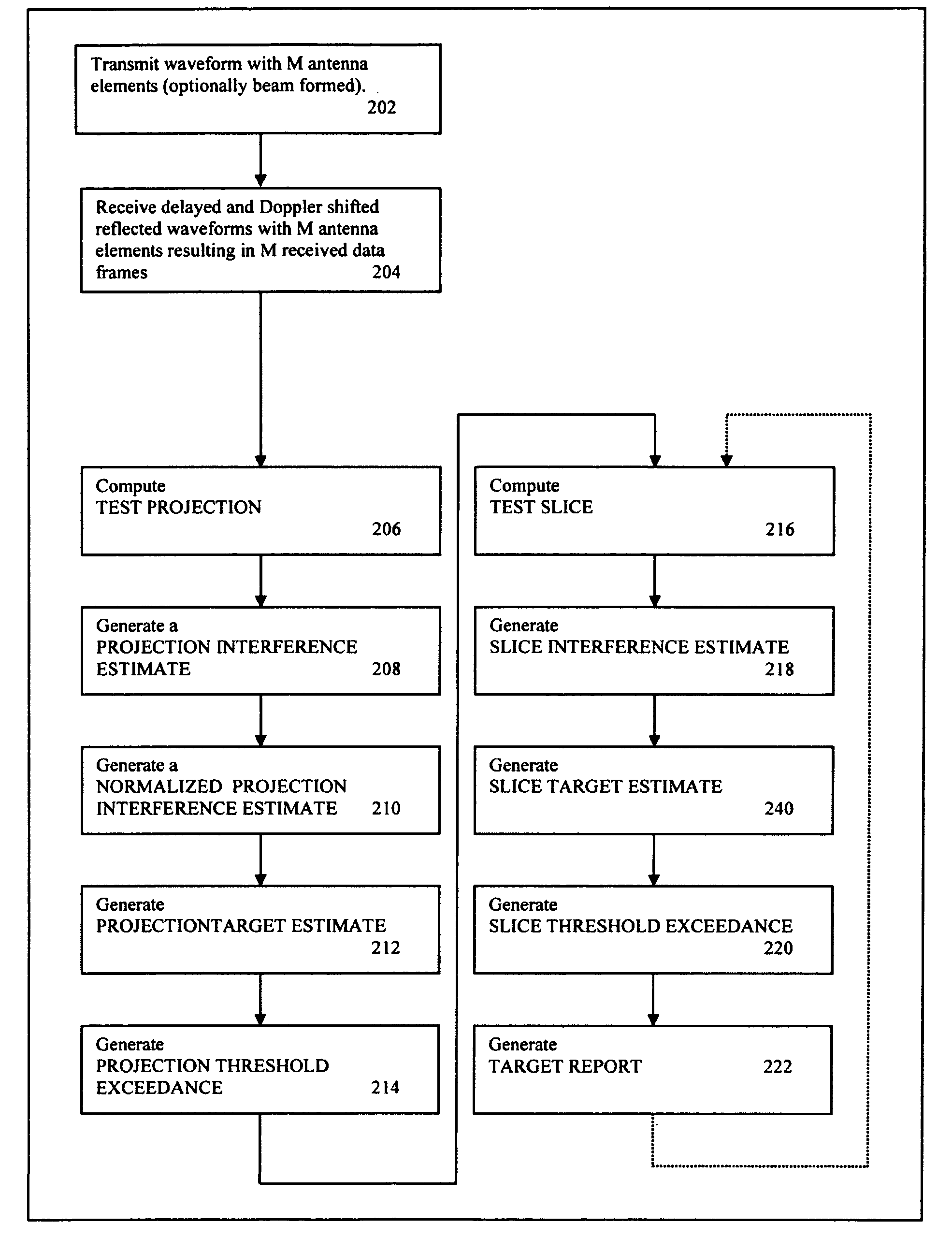
Systems and method of detection and discrimination of targets in the presence of interference are disclosed. A system transmits a signal and then receives signals including interference and reflections of transmitted signals. The system processes the received signals and transmitted signals to generate a 2D representation of the STAP cube with one of the dimensions collapsed. The system then reduces the interference contributions and identifies angle and Doppler component of potential targets. The system then computes slices, which are one dimensional representation of cross-ambiguity functions of the received and transmitted signals. It reduces the interference contributions in the slices and determines range components of the targets.

Description

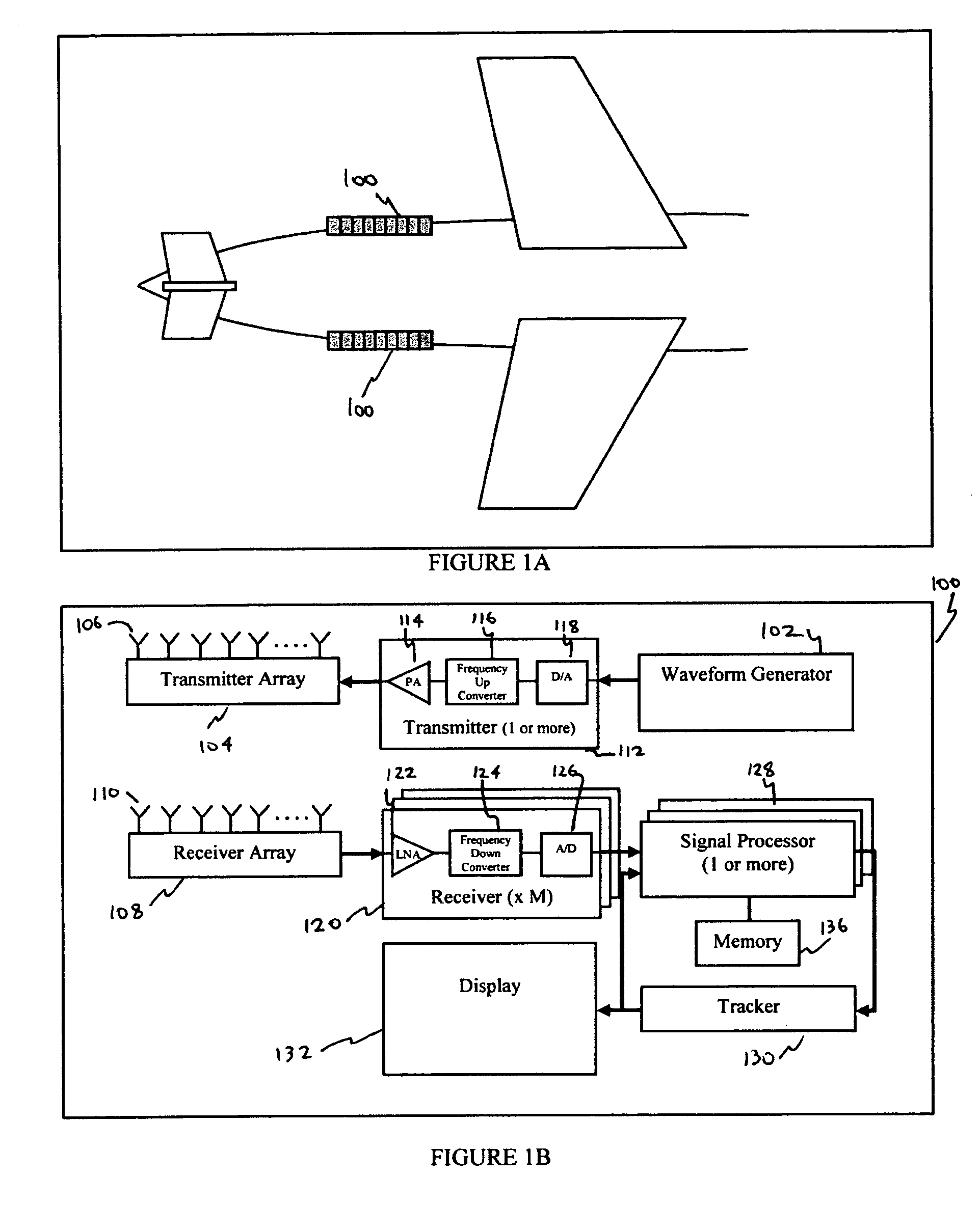
CLAIM OF PRIORITY AND INCORPORATION BY REFERENCE[0001]This application claims priority of provisional application Ser. No. 60 / 687,661, which is incorporated herein by reference. U.S. Pat. No. 6,636,174, U.S. application Ser. No. 09 / 875,116 (Pub. No. 2002 / 0030623), application Ser. No. 10 / 691,245 (Pub. No. 2004 / 0085241), and application Ser. No. 11 / 180,811 (Pub. No. 2006 / 0082491) are also incorporated herein by reference for all purposes.FIELD OF INVENTION[0002]This invention relates generally to Space-Time Adaptive Processing (STAP) technology and more particularly to computationally effective discrimination, detection and tracking of targets in the presence of interference, such as environmental clutter and intentional jamming.BACKGROUND OF INVENTION[0003]A typical prior art STAP system comprises a phased-array antenna with N transmit elements and N receive elements. The receiver antenna gain pattern can be steered in a desired direction through a beam forming process. The STAP sys...

Claims


Application Information

Patent Timeline
Patent Type & Authority Applications(United States)
IPC IPC(8): G01S13/00
CPCG01S7/292G01S7/295G01S13/723G01S13/325G01S13/52G01S13/22
Inventor ARIKAN, ORHANGUMAS, DONALD SPYRO
Owner SIGNAL LABS
Learn More