A single-degree-of-freedom active ankle prosthesis based on a closed hydraulic drive system
What is Al technical title?
Al technical title is built by PatSnap Al team. It summarizes the technical point description of the patent document.
A drive system and degree of freedom technology, applied in prosthesis, medical science, artificial legs, etc., can solve problems such as slow response speed and insufficient output torque of active prosthetics, so as to reduce power consumption, improve battery life, and reduce peak power required effect
Inactive Publication Date: 2019-02-22
BEIHANG UNIV
View PDF8 Cites 0 Cited by
Summary
Abstract
Description
Claims
Application Information
AI Technical Summary
This helps you quickly interpret patents by identifying the three key elements:
Problems solved by technology
Method used
Benefits of technology
Problems solved by technology
[0005] The purpose of the present invention is to solve the problem of insufficient output torque and slow response speed of existing active prostheses, and provide a single-degree-of-freedom active ankle prosthesis with low power consumption, sufficient power and good flexibility
Method used
Image
Click on the blue label to locate the original text in one second.
Reading with bidirectional positioning of images and text.
Examples
Embodiment Construction
[0035] The present invention will be further described in detail with reference to the accompanying drawings and embodiments.
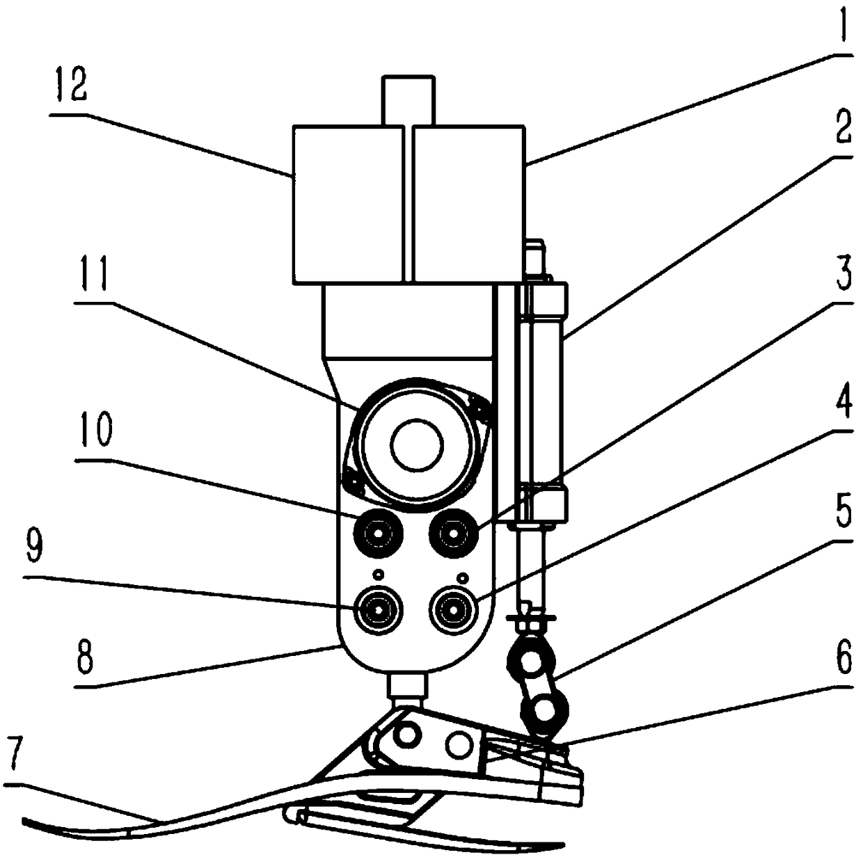
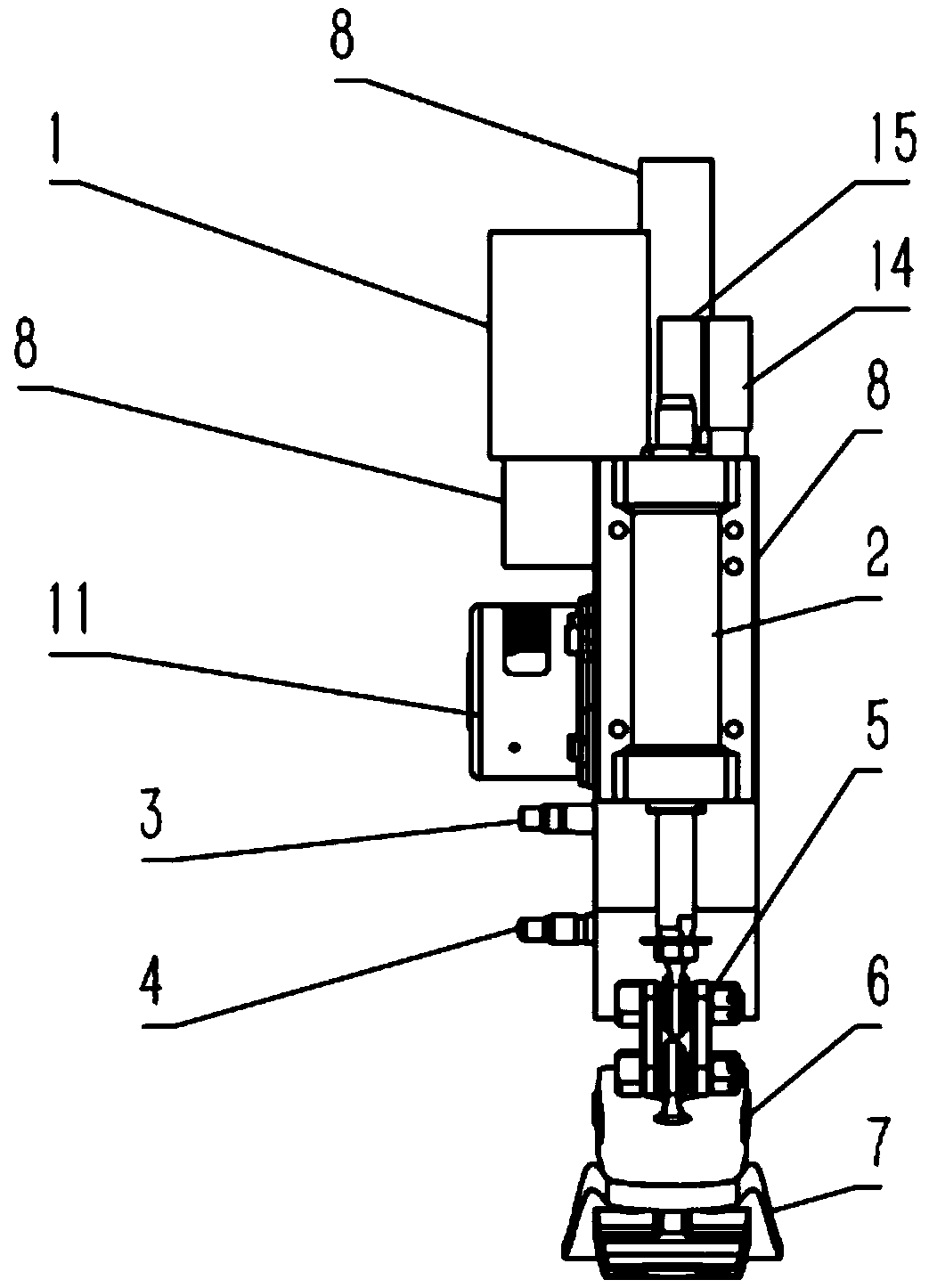
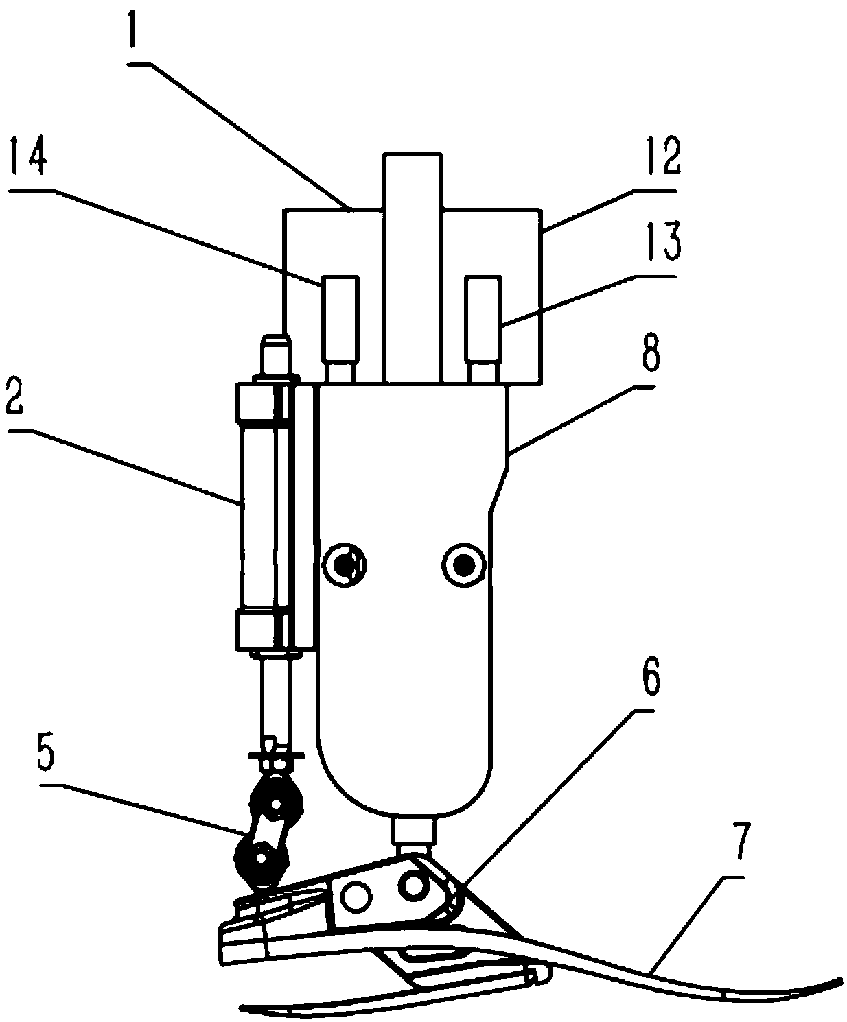
[0036] The present invention is a single-degree-of-freedom active ankle joint prosthesis based on a closed hydraulic circuit system, such as figure 1 , figure 2 , image 3 , Figure 4 , including carbon fiber foot plate 7, micro hydraulic pump 11, hydraulic manifold 8, second accumulator 12, first accumulator 1, first pressure sensor 13, second pressure sensor 14, third pressure sensor 15, first Normally closed switch valve 3, second normally closed switch valve 10, first normally open switch valve 4, second normally open switch valve 9, double rod hydraulic cylinder 2, connecting hinge 5, ankle connecting frame 6.
[0037] The main body of the hydraulic manifold 8 is a rectangular parallelepiped, and on its top, a first accumulator 1 , a second accumulator 12 , a first pressure sensor 13 , a second pressure sensor 14 , and a third pressure sensor...
PUM
Abstract
The invention discloses a single-degree-of-freedom active ankle prosthesis based on a closed hydraulic drive system, including a carbon fiber foot plate, a micro hydraulic pump, a hydraulic integrated block, a first accumulator, a second accumulator, and a first pressure sensor , the second pressure sensor, the third pressure sensor, the first normally closed switch valve, the second normally closed switch valve, the first normally open switch valve, the second normally open switch valve, the double rod hydraulic cylinder, the first one-way valve , the second one-way valve, the third one-way valve, the fourth one-way valve, the connecting hinge, and the ankle connecting frame; compared with the passive ankle joint prosthesis, the present invention enables the wearer to obtain a biological similarity to the human body by actively providing the driving force. The characteristic walking gait improves the wearing comfort of the amputee; in the passive mode, the shock absorption of the hydraulic cylinder can be used to provide damping; in the present invention, the continuous rotation of the motor driven by the hydraulic pump and the energy storage of the accumulator can reduce the impact on The peak power requirements of hydraulic pumps and motors, and reduce power consumption during long-term walking to improve endurance.
Description
technical field [0001] The invention relates to the mechanical structure design of an active power-assisted hydraulic ankle joint prosthesis composed of a single plunger hydraulic pump, an electromagnetic switch valve, a bladder type accumulator and a double-outlet rod hydraulic cylinder. Background technique [0002] In order to help the physically disabled recover their self-care ability and work ability, improve their quality of life, and develop and develop modern and comfortable prosthetic products for the disabled, it has become an important and arduous task for the prosthetic industry at home and abroad. As an important part of the lower limb joints of the human body, the ankle joint has been lagging behind in research all the time, and related prosthetic ankle joint products have not been able to meet the needs of prosthetic patients well. [0003] Active ankle prostheses have significantly improved gait coordination compared to traditional passive ankle prostheses. ...
Claims
Application Information
Patent Timeline
Application Date:The date an application was filed.
Publication Date:The date a patent or application was officially published.
First Publication Date:The earliest publication date of a patent with the same application number.
Issue Date:Publication date of the patent grant document.
PCT Entry Date:The Entry date of PCT National Phase.
Estimated Expiry Date:The statutory expiry date of a patent right according to the Patent Law, and it is the longest term of protection that the patent right can achieve without the termination of the patent right due to other reasons(Term extension factor has been taken into account ).
Invalid Date:Actual expiry date is based on effective date or publication date of legal transaction data of invalid patent.