
Method for dimming the light emitted from LED lights, in particular in the passenger cabin of an airliner

a technology of led lights and passenger cabins, which is applied in the direction of electric variable regulation, process and machine control, instruments, etc., can solve the problems of inability to produce current sinks which switch sufficiently quickly using low-cost components, and difficulty in discharge of natural capacitances within leds, etc., to improve light resolution and color locus gamut, shorten current flow time intervals, and increase the effect of dimming ratio

Active Publication Date: 2009-01-29
DIEHL AEROSPACE GMBH
View PDF9 Cites 12 Cited by
  • Summary
  • Abstract
  • Description
  • Claims
  • Application Information

AI Technical Summary

Benefits of technology

[0009]Accordingly, in order to obviate the foregoing limitations, the present invention is based on solving the technical problem of developing a method of this generic type such that, even with restricted processor capacity and, in conjunction with current sinks using bipolar circuit technology, which is available at low cost since it is conventional, extremely low, that is to say low-light dimming settings can be predetermined reproducibly for LEDs, and can then also be varied finely.
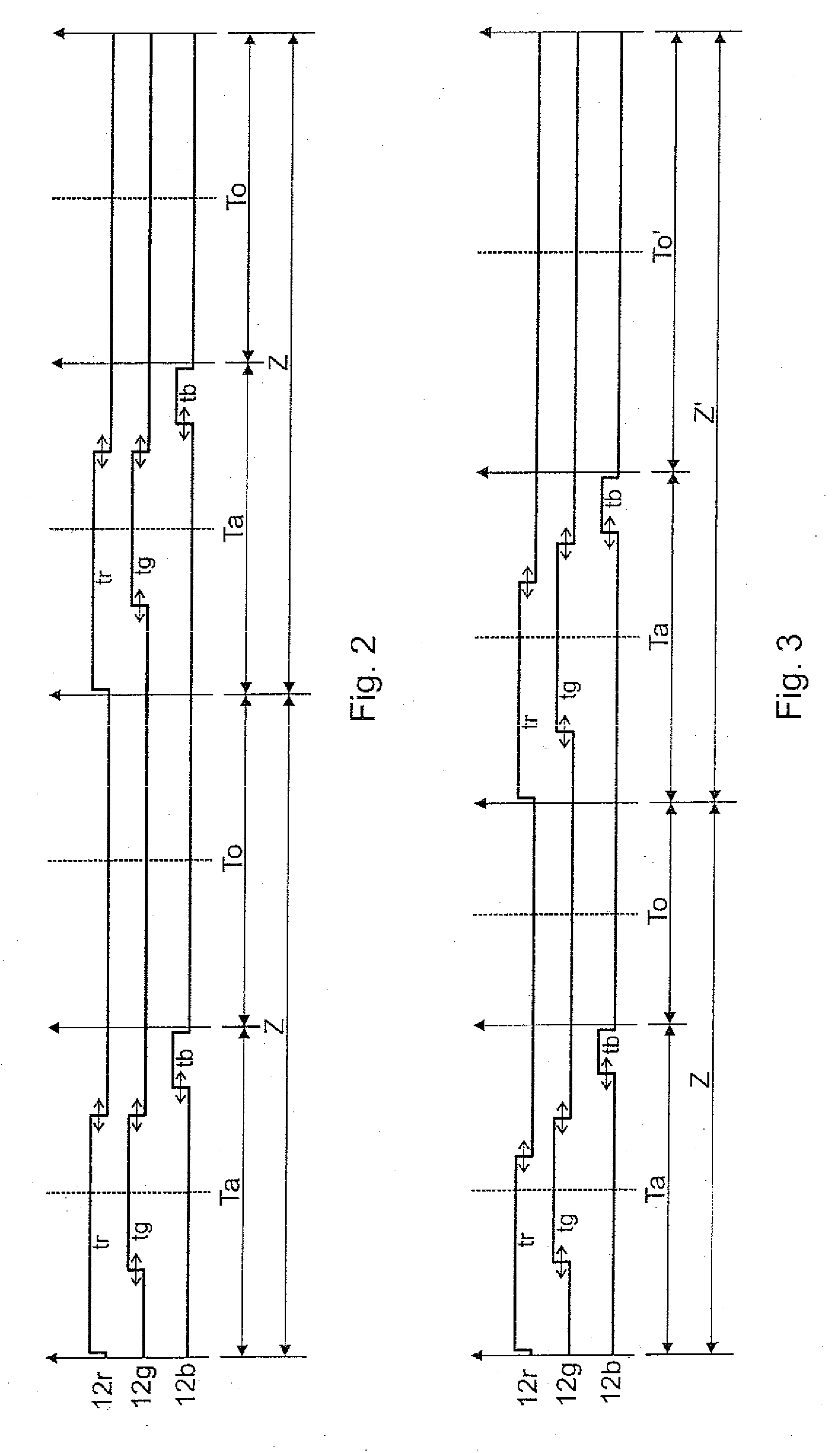
[0010]This object is achieved by the substantial features specified in the main claim. This results in a drive cycle for the LEDs which are subject, so to speak, to superimposed low-frequency modulation. In particular as the cycle is lengthened, the current integral over the cycle is reduced, despite the current-flow time interval not being shortened any further, that is to say without having to reduce the duty ratio of the working period further for the further reduction in the emission from the LEDs that then occurs.
[0013]In order to avoid a color shift or a sudden change in brightness when the number or the length of the no-load periods in one cycle is varied, this switching is expediently carried out at the end of a cycle comprising a working period and no-load periods, the pulse duration in the LED arrays can be set to a temporarily constant cycle current integral in order to prevent any certain change in the current integral occurring at this moment, that is to say avoid a brightness fluctuation and an abrupt current change.
[0014]Finally, the length of the working periods in which the current pulses of constant length occur can also be varied in the successive cycles in order to influence the current integral over the cycle, which governs the brightness of the emitted radiation, without having to shorten the current-flow time intervals even further for further dimming.
[0015]The critical factor according to the invention is therefore that the shortest current-flow time interval which can still be managed without problems using bipolar technology for the current sinks and with a processor with an accepting coding depth need not be shortened any further for further dimming, but can then remain constant because the cycle is now lengthened in the form of superimposed frequency modulation. The resultant current flow is now varied by variation of the cycle lengths for the diode arrays, in particular by being reduced even further, without changing the current-flow time interval itself and in particular without having to reduce it further. In consequence, there is no need to increase the coding depth on the processor used to drive the current sinks in the array in the sense of finer graduation of the current-flow time intervals and this therefore also leads to the current sinks not themselves being driven with radio frequency, as a result of which the hardware technology that has been introduced can still be used despite the considerably increased dimming ratio.
[0016]Visually, this noticeably improves the light resolution and color locus gamut (the described compensation for color locus displacement in an LED by minimal current-flow changes in the two other LEDs). The dimming ratio which is required for this purpose and is achieved according to the invention is considerably greater than 1:10,000, which would not be achievable using analogue circuit technology, therefore allowing a wide brightness dynamic range while ensuring a high level of color locus realism down to very low light emission brightness levels, to which the human eye, which is adapted to instantaneously relatively brightest color, reacts in a manner which is particularly sensitive to color.

Problems solved by technology

Passing current pulses that are as short as this through LEDs results in numerous problems.
For example, these short pulses have fundamental frequencies of several hundred kilohertz, and this can lead to disturbing interference (electromagnetic interference) and frequencies which are allocated to specific radio services (for example the emergency radio at 200 kHz); excessively short-switched-off times make it difficult to discharge the natural capacitances within the LEDs; and it is not possible to produce current sinks which switch sufficiently quickly using low-cost components.
Such extreme LED dimming would be feasible from the circuitry point of view only by using very fast and therefore expensive processes with a high coding depth for the fine subdivision of the working period, together with high-power, radio-frequency transistors for the current sinks in the R, G and B diode series circuit, that is to say with a rarely acceptable level of circuitry complexity.

Method used


Image

  • Method for dimming the light emitted from LED lights, in particular in the passenger cabin of an airliner
  • Method for dimming the light emitted from LED lights, in particular in the passenger cabin of an airliner
  • Method for dimming the light emitted from LED lights, in particular in the passenger cabin of an airliner

Examples


Embodiment Construction

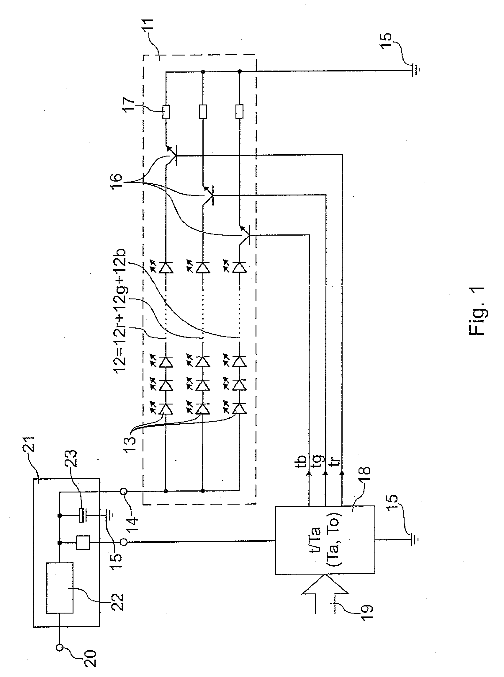
[0022]The light 11 represented symbolically in FIG. 1 has in each case one array 12 (12r, 12g and 12b) whose brightness can be controlled individually formed by series circuits, of red, green and blue light-emitting diodes 13; this sketch ignores the fact that a white-light array, whose brightness is likewise controllable, and composed of LEDs which intrinsically emit blue but are coated with phosphorus is also expedient for fine color correction and in order to influence the color saturation. Each array 12 is connected between a supply voltage 14 (typically of 55 volts) and the appliance earth 15, in the direction of the latter via a constant-current sink 16 in the form of a bipole transistor, connected in the common-emitter form, with its emitter resistance 17.

[0023]A commercially available microprocessor 18 with a coding depth of typically 2 exp 4=16 bits time resolution within one working period Ta in each case switches on the transistors in the constant-current sinks 16 indepen...


PUM


Abstract

In order to dim the brightness of the mixed-color light from an LED light (11) with LED arrays (12r, 12g, 12b) which emit different colors, in particular in the passenger cabin of an airliner, the current-flow time intervals (tr, tg, tb) which can be adjusted such that they are different over the various arrays (12) are shortened in steps during initially constant working period lengths (ta).

Description

BACKGROUND OF THE INVENTION[0001]1. Field of the Invention[0002]The invention relates to a method for the dimming of the light emitted from LED lights, and in particular, in the passenger cabin of an airliner.[0003]2. Discussion of the Prior Art[0004]DE 102005 016 729 B3 discloses the dimming of the light emitted from a white-light light-emitting diode (LED) in successive working periods without any gaps and of the same length as one another, in each of which high-frequency chopping takes place of the current which flows during the switched-on time intervals in the successive working periods through the diode. The shorter the switched-on time interval in the working period is, the fewer constant-current pulses flow through the LED and in consequence the lower is the brightness of the emitted light.[0005]In order to vary the color impression of an LED light, the light emitted from LED arrays in the primary colors red, green and blue is normally superimposed with different intensity, ...

Claims


Application Information

Patent Timeline
IPC IPC(8): H05B41/36H05B44/00
CPCH05B33/0815H05B33/086H05B33/0818H05B45/37H05B45/20
Inventor POHLER, ULRICH
Owner DIEHL AEROSPACE GMBH
Learn More