
Cooling fan drive system for travel type working machine

Active Publication Date: 2009-01-29
HITACHI CONSTR MASCH CO LTD
View PDF2 Cites 24 Cited by
  • Summary
  • Abstract
  • Description
  • Claims
  • Application Information

AI Technical Summary

Benefits of technology

[0021]Accordingly, the rotational speed of the cooling fan is controlled to the optimum rotational speed in accordance with the temperature increase of the engine cooling water, and also the rotational speed of the engine can be smoothly increased when the rotational speed of the engine under travel acceleration is increased. As a result, the working efficiency can be enhanced, and also deterioration of exhaust gas is little, so that there is little concern about environment pollution.

Problems solved by technology

Furthermore, the hydraulic pump and the torque-converter require hydraulic operating fluid.

Method used


Image

  • Cooling fan drive system for travel type working machine
  • Cooling fan drive system for travel type working machine
  • Cooling fan drive system for travel type working machine

Examples


Embodiment Construction

[0077]Embodiments of the invention will be described hereunder with reference to the drawings.

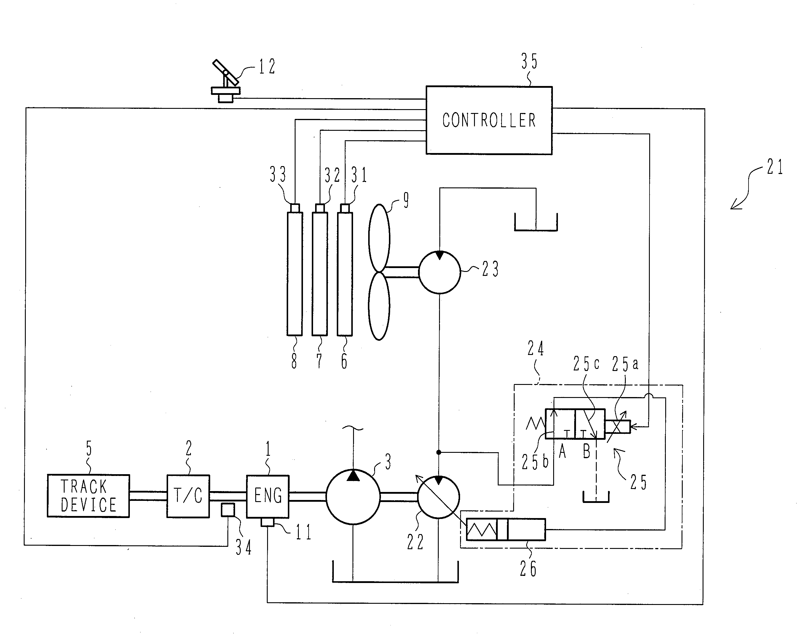
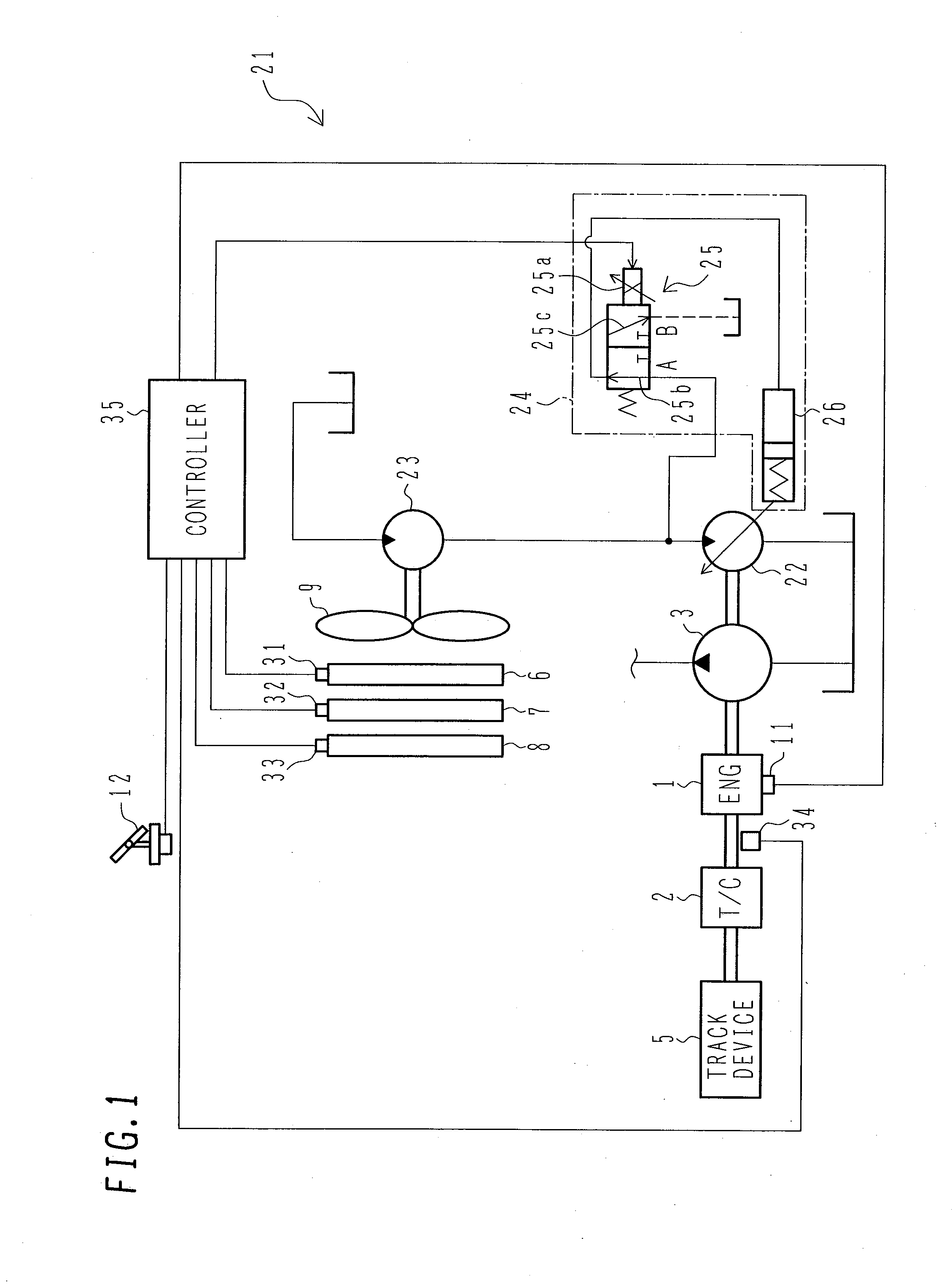
[0078]FIG. 1 is a diagram showing a cooling fan drive system for a travel type working machine according to a first embodiment of the invention together with the surrounding construction thereof.

[0079]In FIG. 1, the travel type working machine according to this embodiment has a diesel engine as a motor (hereinafter referred to as engine”) 1, and a torque converter 2 and a hydraulic pump 3 which are driven by the engine 1. The torque converter 2 is linked to the travel device 5, and the driving force of the engine 1 is transmitted through the torque converter 2 to the travel device 5. The travel device 5 has a transmission, a differential gear, an axle, front wheels, rear wheels, etc. (not shown), and drives the front wheels and the rear wheels by the driving force of the engine 1 transmitted through the torque converter 2, thereby generating traveling force. The hydraulic pump 3 is rotation...


PUM


Abstract

In a cooling fan drive system for a travel type working machine, the rotational speed of a cooling fan is controlled to the optimum rotational speed in accordance with temperature increase of the temperature of an engine cooling water, and the engine rotational speed is smoothly increased when the engine rotational speed is increased under travel acceleration. A fourth fan target rotational speed calculator 35e and a minimum value selector 35f are provided, and under non-operation, the fan target rotational speed is set to a low rotational speed irrespective of the temperature. When an acceleration pedal 12 is depressed to increase the rotational speed of the engine under travel acceleration, the increase of the drive pressure of a hydraulic motor 23 due to increase of the rotation of the cooling fan 9 is suppressed, and the load on the engine 1 is reduced.

Description

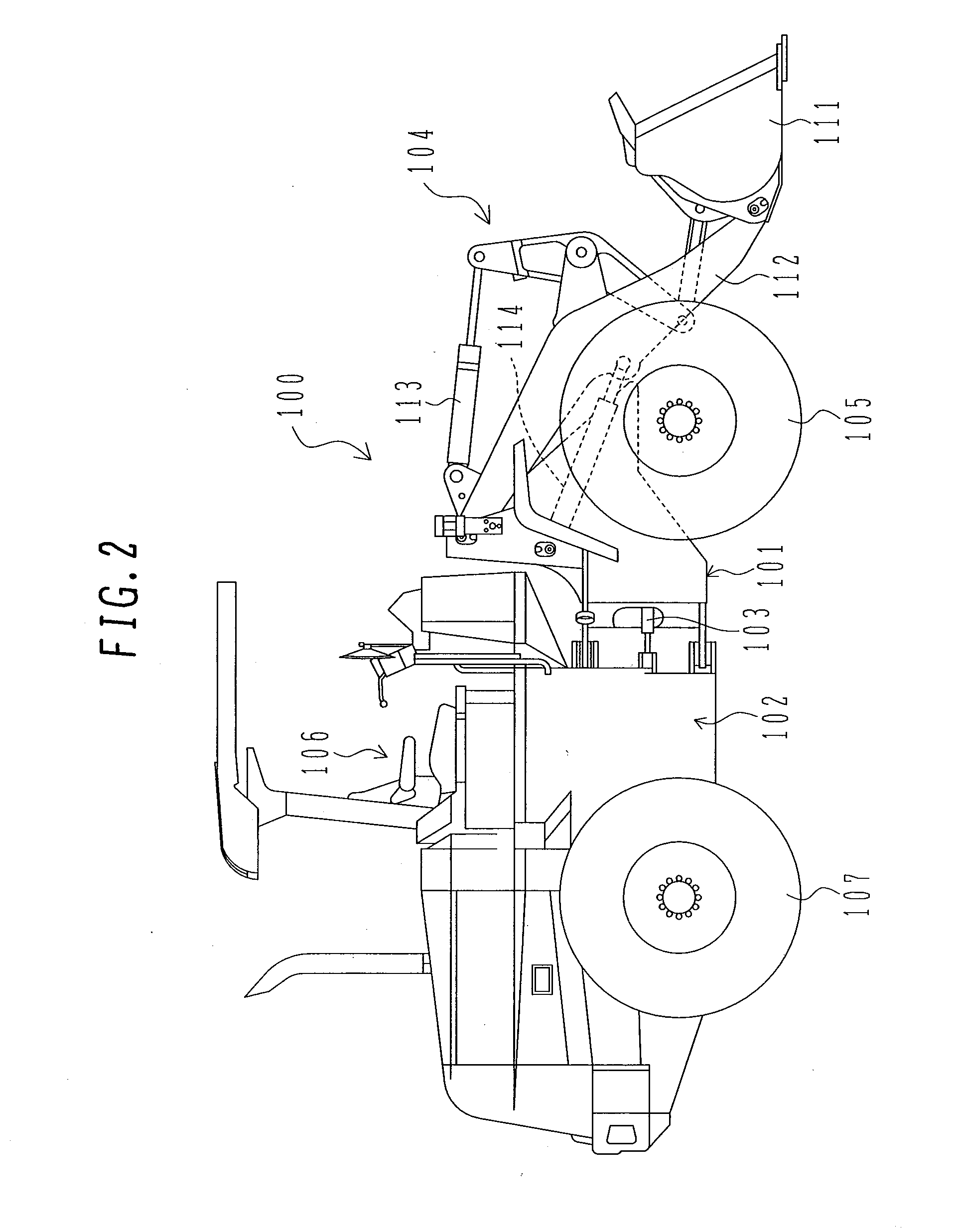
TECHNICAL FIELD[0001]The present invention relates to a cooling fan drive system for a travel type working machine such as a load working vehicle such as a wheel loader, a telehandler or the like, a construction machine such as a wheel type hydraulic shovel, a crawler type hydraulic shovel or the like.BACKGROUND ART[0002]In a traveling type working machine such as a wheel loader or the like which is a representative of load working vehicles, a hydraulic pump and a torque-converter are driven by an engine to thereby drive respective working machines and track devices.[0003]The engine is cooled by circulating a coolant (engine cooling water) to the main body of the engine. The coolant heated in the engine is passed through a radiator to be cooled, and then returned into the engine. Furthermore, the hydraulic pump and the torque-converter require hydraulic operating fluid. The hydraulic operating fluid is cooled by leading the hydraulic operating fluid to the respective oil coolers.[00...

Claims


Application Information

Patent Timeline
IPC IPC(8): F01P7/04
CPCE02F9/226F01P7/044F01P2025/66F01P2025/62F01P2023/08F01P7/04E02F9/00
Inventor ITOGA, KENTAROUNAKAMURA, TSUYOSHINAKAMURA, KAZUNORI
Owner HITACHI CONSTR MASCH CO LTD
Learn More