


Quick Research
Generate reliable direction feasibility study reports for your R&D in just a few steps.

Technical Q&A
Discover and master advanced knowledge NOW. Basics, ideas, possibilities, all at once.

Find Solutions
As an expert in R&D theories, this can generate solutions to your technical problems instantly.

Evaluate Feasibility
Analyze your overall solution with one click, know your potential R&D risks in advance.

Monitor Landscape
Get weekly tech updates, stay abreast of the latest tech innovations and key insights.
Fuel Cell
a fuel cell and cell technology, applied in the field of fuel cells, can solve the problems of deterioration in the durability of the fuel cell, insufficient electrolyte force, oxidation degradation of the polymer electrolyte of the mea, etc., and achieve the effect of improving the durability, reducing the amount of hydrogen peroxide gathered in the spaces, and improving the durability
- Summary
- Abstract
- Description
- Claims
- Application Information
AI Technical Summary
Benefits of technology
Problems solved by technology
Method used
Image

Examples
first embodiment
1. FIRST EMBODIMENT
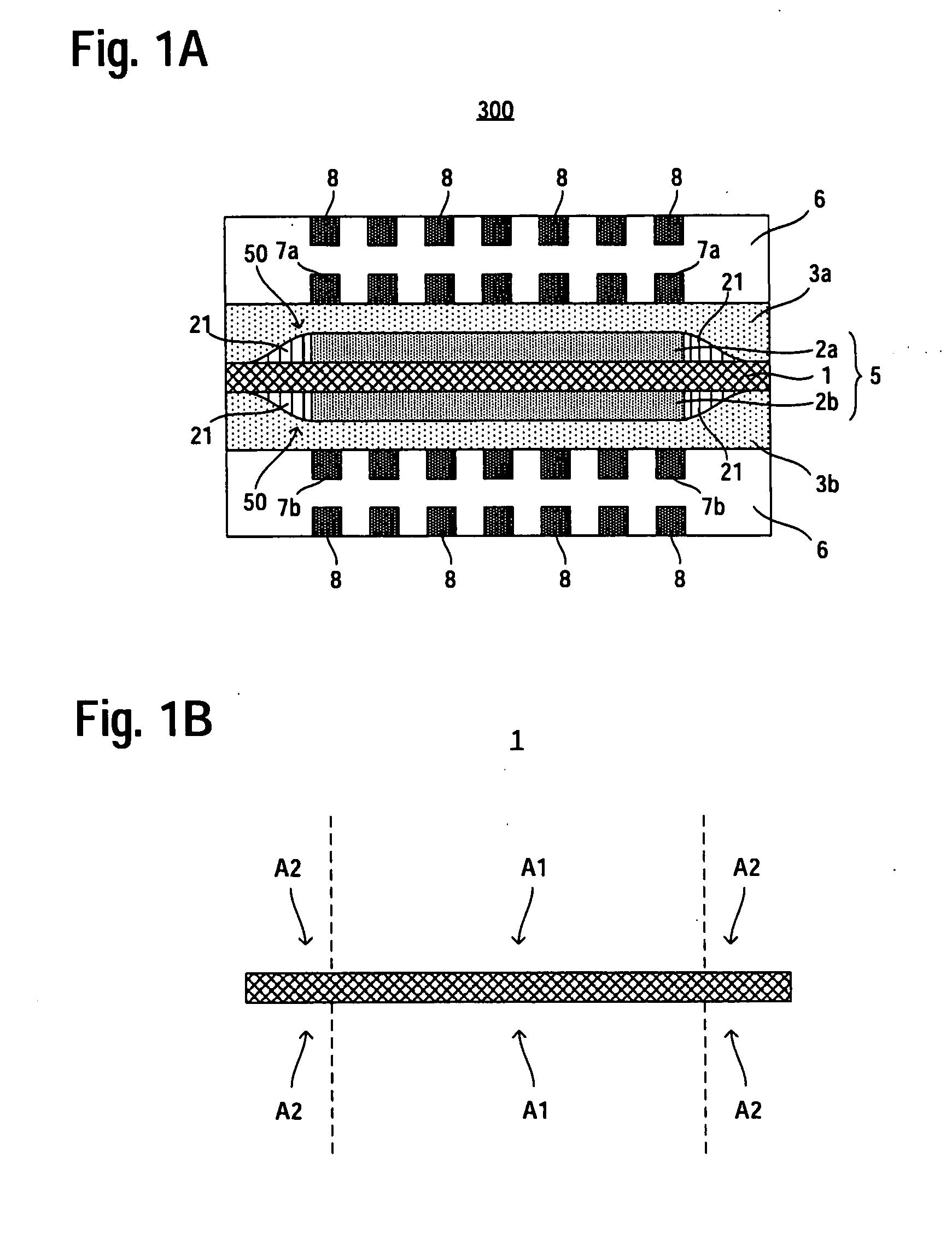
[0032]FIG. 1 is a cross-sectional view schematically showing a fuel cell according to a first embodiment of the present invention and an electrolyte membrane of the fuel cell, respectively. In FIG. 1, vertical direction corresponds to a stacking direction of catalyst layers. More specifically, FIG. 1A is a cross-sectional view schematically showing the fuel cell according to the first embodiment of the present invention. FIG. 1B is a cross-sectional view showing only the electrolyte membrane shown in FIG. 1A. In FIG. 1, constituent elements or regions similar in configuration to those of the conventional fuel cell shown in FIG. 4 are denoted by the same reference symbols as those used in FIG. 4 and will not be often described herein. Furthermore, the anode catalyst layer and the cathode catalyst layer are often referred to simply “catalyst layers”.
[0033]As shown in FIG. 1A, a fuel cell 100 according to the first embodiment includes an MEA 5 that includes an electr...
second embodiment
2. SECOND EMBODIMENT
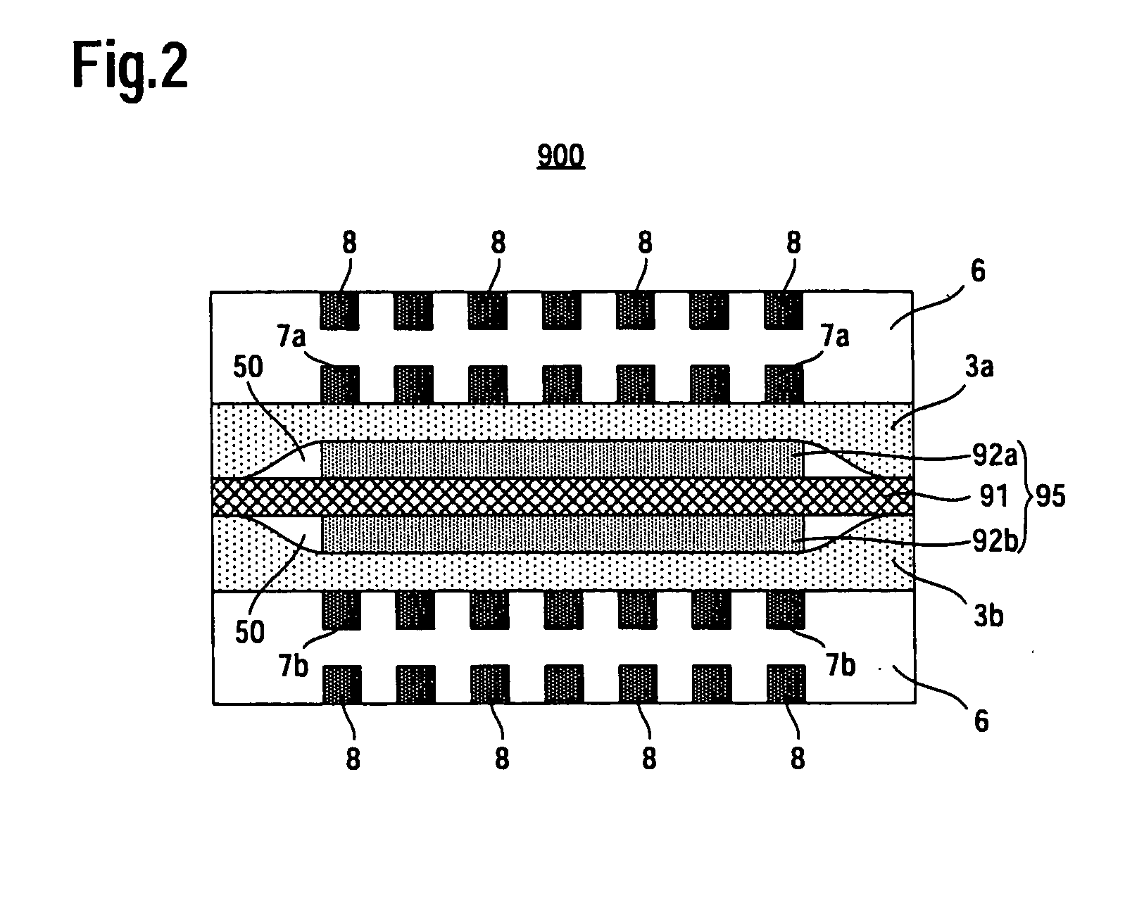
[0038]FIG. 2 is a cross-sectional view schematically showing a fuel cell according to a second embodiment of the present invention. In FIG. 2, vertical direction corresponds to a stacking direction of catalyst layers. In FIG. 2, constituent elements or regions similar in configuration to those of the conventional fuel cell shown in FIG. 1 are denoted by the same reference symbols as those used in FIG. 1 and will not be often described herein.
[0039]As shown in FIG. 2, a fuel cell 200 according to the second embodiment includes an MEA 5 that includes an electrolyte membrane 1 and an anode catalyst layer 2a and a cathode catalyst layer 2b which are arranged on both sides of the electrolyte membrane 1, respectively, an anode diffusion layer 3a and a cathode diffusion layer 3b arranged on both sides of the MEA 5, respectively, and separators 6, 6 arranged outside of the anode diffusion layer 3a and the cathode diffusion layer 3b, respectively. On each of the surfaces ...
third embodiment
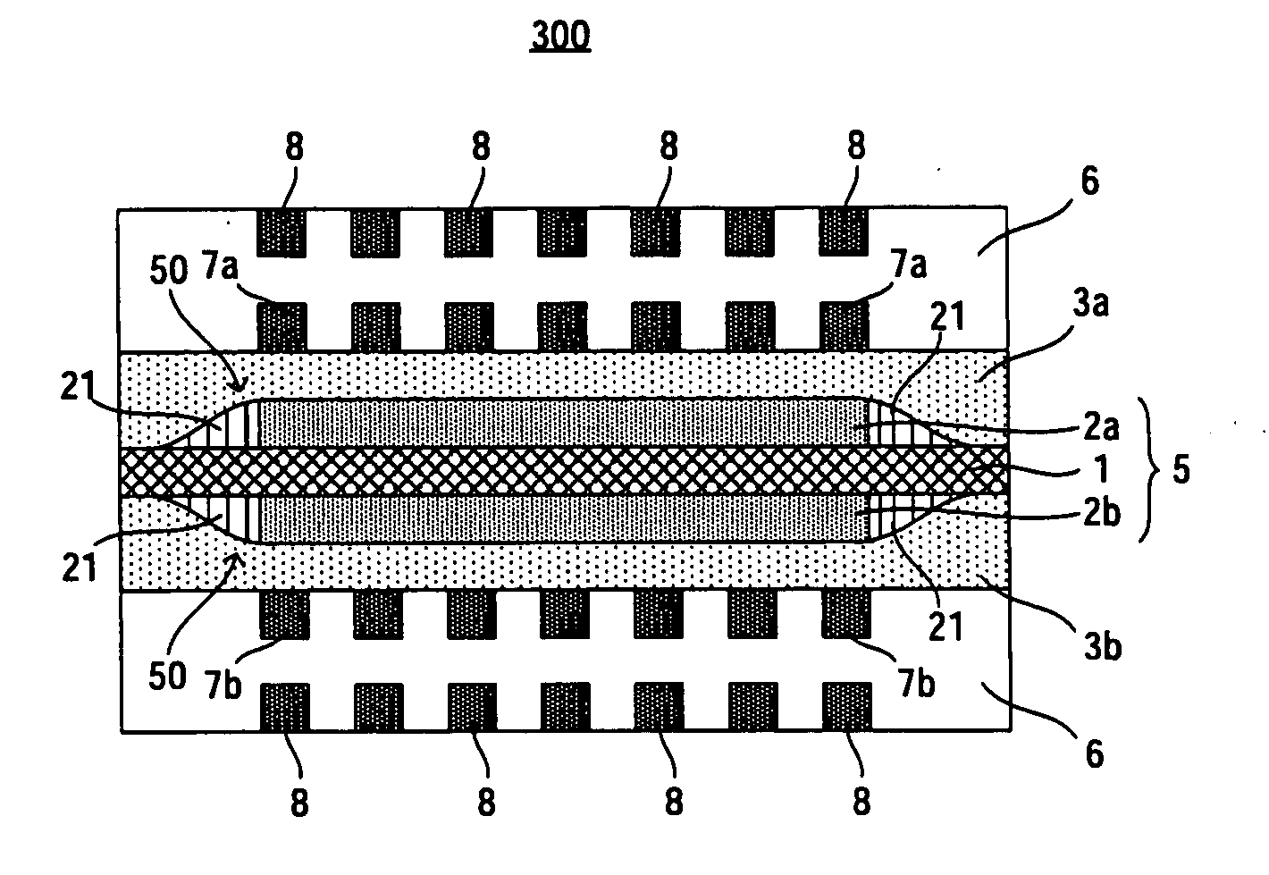
3. THIRD EMBODIMENT
[0041]FIG. 3 is a cross-sectional view schematically showing a fuel cell according to a third embodiment of the present invention. In FIG. 3, vertical direction corresponds to a stacking direction of catalyst layers. In FIG. 3, constituent elements or regions similar in configuration to those of the conventional fuel cell shown in FIG. 2 are denoted by the same reference symbols as those used in FIG. 2 and will not be often described herein.
[0042]As shown in FIG. 3, a fuel cell 300 according to the third embodiment includes an MEA 5 that includes an electrolyte membrane 1 and an anode catalyst layer 2a and a cathode catalyst layer 2b which are arranged on both sides of the electrolyte membrane 1, respectively, an anode diffusion layer 3a and a cathode diffusion layer 3b arranged on both sides of the MEA 5, respectively, and separators 6, 6 arranged outside of the anode diffusion layer 3a and the cathode diffusion layer 3b, respectively. On each of surfaces A2, A2,...
PUM
| Property | Measurement | Unit |
|---|---|---|
| electromotive force | aaaaa | aaaaa |
| durability | aaaaa | aaaaa |
| electric energy | aaaaa | aaaaa |
Abstract
Description
Claims
Application Information
 - R&D Engineer
- R&D Manager
- IP Professional
- Industry Leading Data Capabilities
- Powerful AI technology
- Patent DNA Extraction
Browse by: Latest US Patents, China's latest patents, Technical Efficacy Thesaurus, Application Domain, Technology Topic, Popular Technical Reports.
© 2024 PatSnap. All rights reserved.Legal|Privacy policy|Modern Slavery Act Transparency Statement|Sitemap|About US| Contact US: help@patsnap.com