
Systems and methods for a RFID enabled metal license plate

Active Publication Date: 2009-01-22
NEOLOGY INC
View PDF11 Cites 42 Cited by
  • Summary
  • Abstract
  • Description
  • Claims
  • Application Information

AI Technical Summary

Benefits of technology

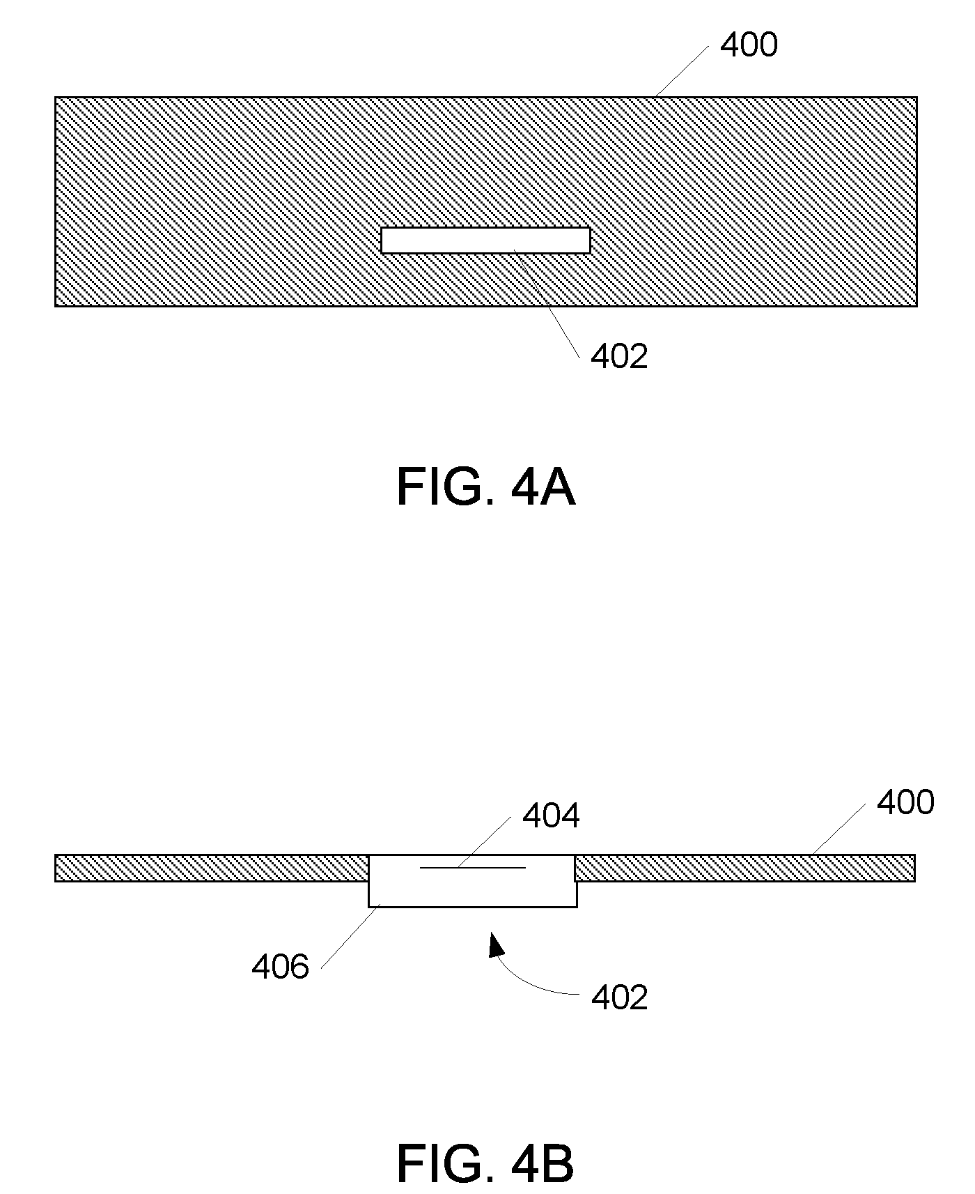
[0018]For example, in one aspect, such an RFID enabled license plate can include a metal license plate with a slot formed in the metal license plate, and a RFID tag module positioned in the slot. The RFID tag module can include a chip and a loop, and the loop can be coupled with the metal license plate, e.g., via inductive or conductive coupling. In this manner, the metal license plate can be configured to act as a resonator providing increased performance.

Problems solved by technology

The owner is then provider a sticker, which is applied to the vehicle license plate, to evidence the valid registration of the vehicle; however, these stickers can easily be counterfeited or stolen, i.e., removed and applied to another vehicle.
Such activity is difficult to detect, because the only way to determine that a registration sticker does not belong on a certain vehicle is to access a database and check the corresponding information.
For example, in the United States, an estimated five to ten percent of motorists fail to legally register their vehicles, resulting in lost annual state revenues of between $720 million and $1.44 billion.
This has the convenience an continuity of replicating the application of current registration stickers; however, such a solution can also suffer from reduced transmission, i.e., communication distance due to the effects the metal license plate has on the performance of the tag antenna.
As a result, the tag information may not be readable due to the shielding effects of metal surrounding tag 100.
One problem with such a conventional solution is the increased dimension, i.e., thickness of the resulting license plate assembly.
Accordingly, conventional approaches force a tradeoff between reduced performance, or increased size and dimensions, which can have a negative impact.

Method used


Image

  • Systems and methods for a RFID enabled metal license plate
  • Systems and methods for a RFID enabled metal license plate
  • Systems and methods for a RFID enabled metal license plate

Examples


Embodiment Construction

.”

BRIEF DESCRIPTION OF THE DRAWINGS

[0024]Features, aspects, and embodiments of the inventions are described in conjunction with the attached drawings, in which:

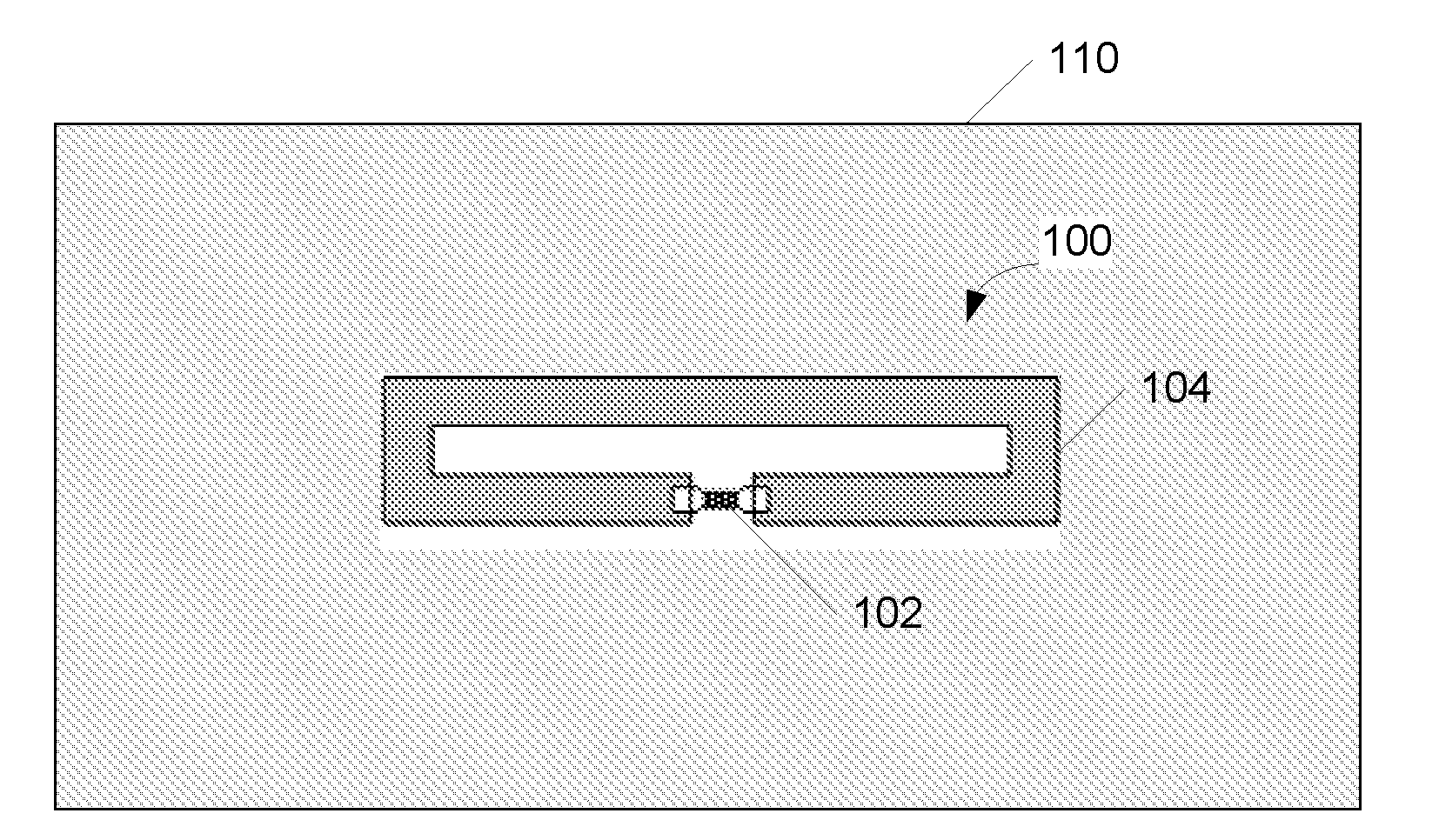
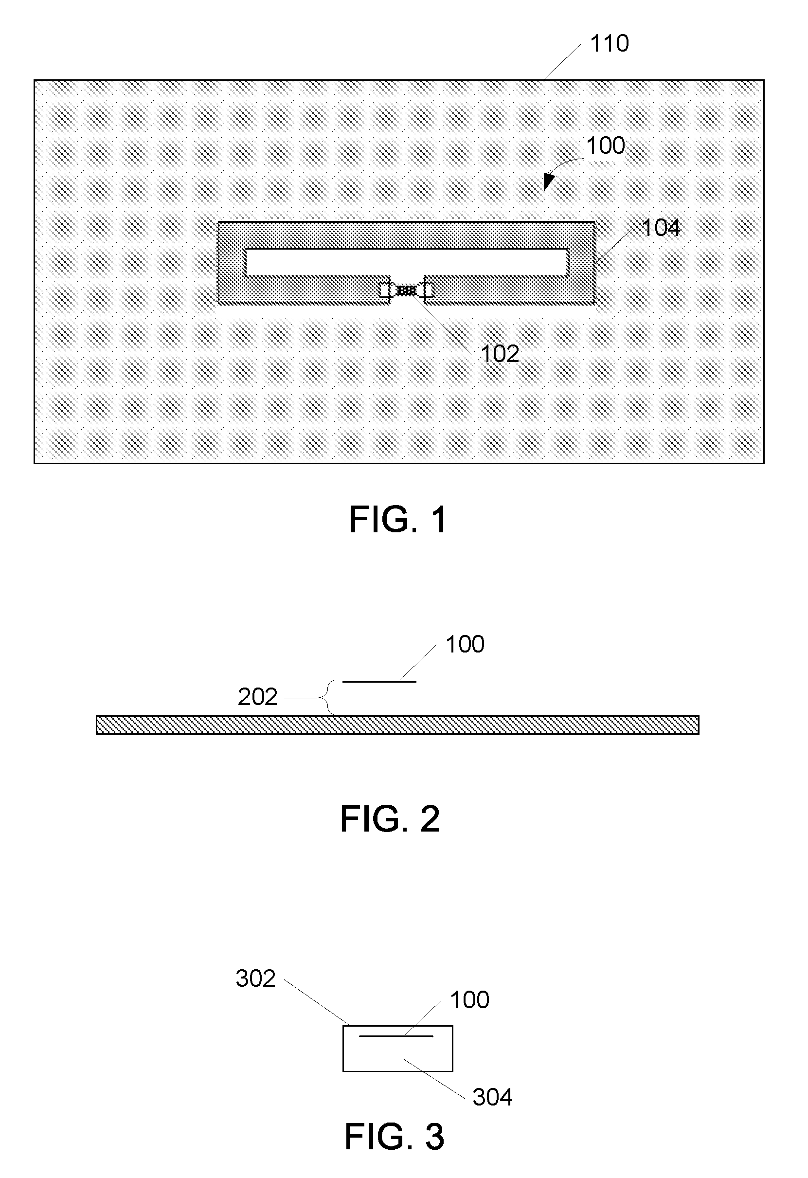
[0025]FIG. 1 is a diagram illustrating an exemplary license plate comprising an RFID module;

[0026]FIG. 2 is a diagram illustrating a side view of the license plate of FIG. 1;

[0027]FIG. 3 is a diagram illustrating a RFID module that can be used in conjunction with the license plate of FIGS. 1 and 2;

[0028]FIGS. 4A and 4B are diagrams illustrating an example RFID enabled license plate in accordance with one embodiment;

[0029]FIGS. 5A and 5B are diagrams illustrating methods for coupling an RFID module with the license plate of FIGS. 4A and 4B;

[0030]FIGS. 6A-C are diagrams illustrating an example RFID enabled license plate in accordance with another embodiment;

[0031]FIGS. 7A-C are diagrams illustrating example RFID enabled license plate in accordance with another embodiment;

[0032]FIG. 8 is a diagram illustrating another example RF...


PUM


Abstract

In the embodiments described herein, a RFID enabled license plate is constructed by using the license plate, or a retro-reflective layer formed thereon as part of the resonator configured to transmit signals generated by and RFID chip integrated with the license plate. Such an RFID enabled license plate can include a metal license plate with a slot formed in the metal license plate, and a RFID tag module positioned in the slot. The RFID tag module can include a chip and a loop, and the loop can be coupled with the metal license plate, e.g., via inductive or conductive coupling. In this manner, the metal license plate can be configured to act as a resonator providing increased performance.

Description

RELATED APPLICATIONS INFORMATION[0001]This application claims the benefit under 35 U.S.C. 119 (e) to U.S. Provisional Patent Application Ser. No. 60 / 871,273, filed Dec. 21, 2006, and entitled “Method and Apparatus for RFID Enabled Metal License Plates”, which is incorporated herein by reference in its entirety as if set forth in full.BACKGROUND[0002]1. Field of the Invention[0003]The embodiments described herein relate generally to electronic vehicle registration and tracking systems, and more particularly to the use of Radio Frequency Identification (RFID) in such systems.[0004]2. Background of the Invention[0005]RFID technology has long been used for electronic vehicle tolling applications. In such applications, an RFID reader or interrogator is position over or near a road way at a point where a toll is to be collected. An RFID tag is then place in each vehicle that includes an identifier by which the vehicle can be recognized, e.g., the vehicle's license plate number. The interr...

Claims


Application Information

Patent Timeline
IPC IPC(8): G08B13/14
CPCG06K19/07749G06K19/07773G06K19/07758G08B13/2434
Inventor ZHU, JEFFREYYEN, CHIH-CHUANLIU, JUNMULLIS, JOE
Owner NEOLOGY INC
Learn More