Particulate sifter
a sifter and particle technology, applied in the field of particle sifter, can solve the problems of reducing the effective shifting area of the net body, affecting the achievement of good manufacturing practice standards, and reducing the performance (the amount of particulates that can be shifted per unit time) of the net body xb>2/b>, so as to prevent a reduction of the net body performance, reduce the loss of measured particulates, and reduce the effect of flowability
- Summary
- Abstract
- Description
- Claims
- Application Information
AI Technical Summary
Benefits of technology
Problems solved by technology
Method used
Image

Examples
first embodiment
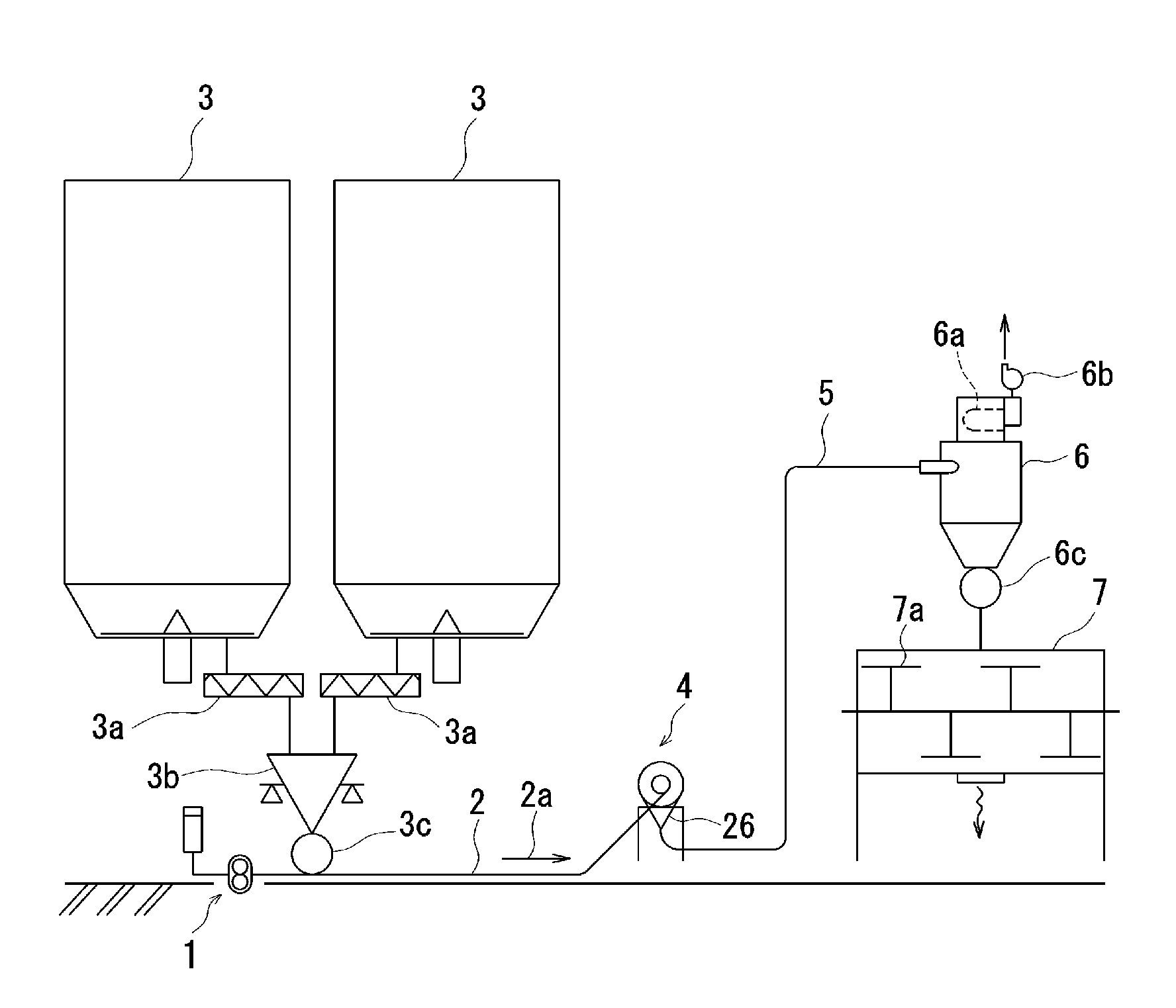
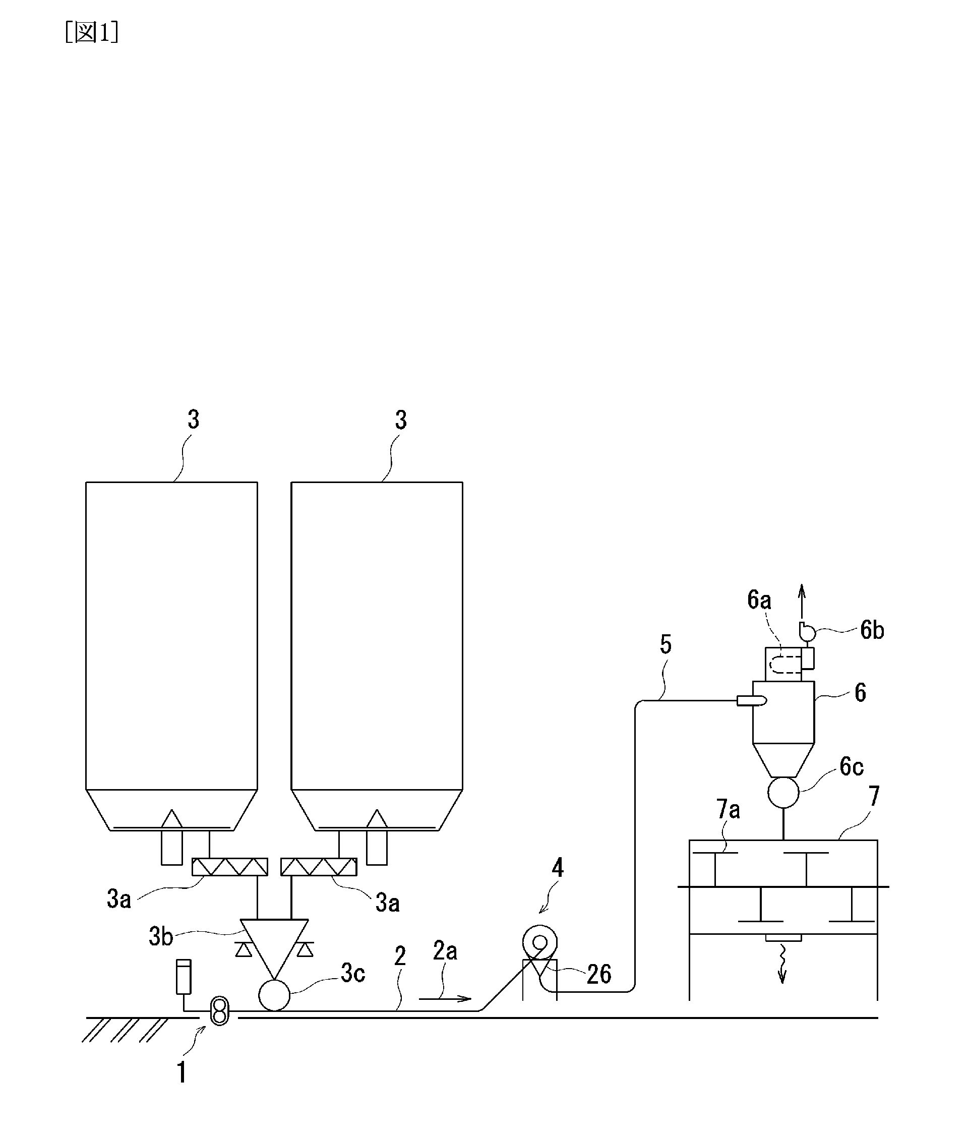
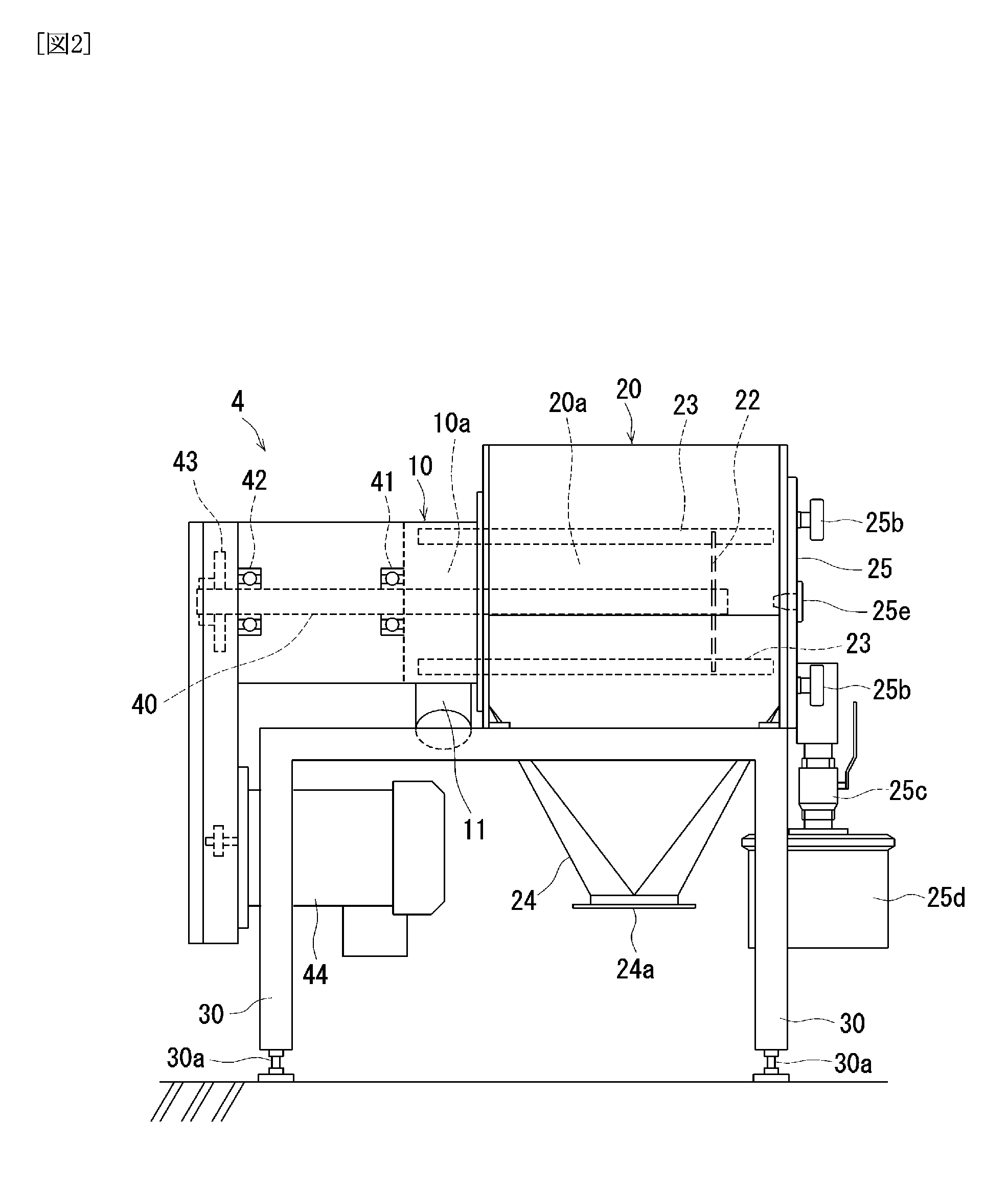
[0053]A particulate sifter according to this embodiment of the invention is an inline type particulate sifter connected to a conveying line in a particulate conveying system shown in FIG. 1. Reference number 1 in FIG. 1 indicates an air supplying means that supplies conveying air (compressed air) into a pipe 2 in order to convey particulates pneumatically. Particulates discharged from stock bins 3 with screw conveyers 3a and measured with an automatic measuring apparatus 3b are injected into the pipe 2 via a rotary valve 3c disclosed in Japanese Patent No. 3336305 and others. The injected particulates are then mixed with the conveying air and conveyed in the pipe 2 as particulate-air mixture in the direction of the arrow 2a.
[0054]A particulate sifter 4 to screen and remove foreign substances in the particulate-air mixture is connected to the pipe 2 at the downstream of rotary valve 3c. The particulate-air mixture from which foreign substances are removed flows into a server 6 via a...
second embodiment
[0089]In the first embodiment described above, the invention is applied to an inline type particulate sifter 4 into which particulate-air mixture comprised of particulates and conveying air flows. On the other hand, in this embodiment, the invention is applied to a gravity type particulate sifter into which particulates are thrown by means of gravity without using conveying air.
[0090]FIG. 9 shows a front view of a particulate sifter 104 according to this embodiment. Components of this embodiment corresponding to those of the first embodiment are numbered with 100 added to the reference number in the first embodiment. And a further explanation is omitted. Although the inlet 11 and the influx hole 10b are located on the bottom side of the influx casing 10 in the inline type particulate sifter 4, an inlet 111 and an influx hole 110b are located on the upper side of a influx casing 110 in a gravity type particulate sifter 104. The inlet 111 is formed in a shape of a hopper, and particul...
third embodiment
[0096]In the particulate sifter 4 of the first embodiment descried above, the first ring member 27 of the net body 26 is supported and rotated by rollers 45b and 46b with the rollers 45b being rotated by the respective electric motors 45M. On the contrary, in a particulate sifter 204 of the third embodiment, location of an electric motor 245M is different from that of the electric motors 45M, and a second ring member 228 located at the downstream of a net body 126 is supported and rotated by the electric motor 245M. Furthermore, the rollers 45, 46 are replaced by a supporting member 245 shown in FIG. 16 and FIG. 17. This supporting member 245 is fitted inside a first ring member 227.
[0097]More specifically as shown in FIG. 10 to FIG. 18, the particulate sifter 204 has an opening 220e located at one end of a casing 220 which is on the downstream side of the flow of particulates and an access door 225 to open and close the opening 220e. The electric motor 245M is fixed on the outer si...
PUM
 Abstract
Description
Claims
Application Information
 - R&D
- Intellectual Property
- Life Sciences
- Materials
- Tech Scout
- Unparalleled Data Quality
- Higher Quality Content
- 60% Fewer Hallucinations
Browse by: Latest US Patents, China's latest patents, Technical Efficacy Thesaurus, Application Domain, Technology Topic, Popular Technical Reports.
© 2025 PatSnap. All rights reserved.Legal|Privacy policy|Modern Slavery Act Transparency Statement|Sitemap|About US| Contact US: help@patsnap.com