
Single-piece forged-steel piston with inner oil cooling chamber and a method for manufacturing thereof

a manufacturing method and technology for forged steel pistons, applied in the field of single-piece forged steel pistons with inner oil cooling chambers, can solve the problems of increasing manufacturing costs, poor cooling effect, and failing to meet the demands of the engine, and achieves the effects of high power, simple structure and easy manufacturing process

Inactive Publication Date: 2009-01-22
LIN FENGHUA +3
View PDF3 Cites 36 Cited by
  • Summary
  • Abstract
  • Description
  • Claims
  • Application Information

AI Technical Summary

Benefits of technology

[0008]Therefore, it is one objective of the present invention to provide a laser welded single piece forged steel piston with an enclosed inner oil cooling chamber having a simple structure and relative easy manufacturing process and capable of satisfying the requirements of high power, high rigidity, and low discharge.

Problems solved by technology

Although a conventional aluminum piston is light, it gradually fails to meet these demands.
However, the separate manufacture of the piston head and the piston skirt increases manufacturing cost.
Moreover, an enclosed oil cooling chamber is difficult to form, resulting in poor cooling effect.
Meanwhile, a long piston pin is often needed for connection, which increases the overall weight of the piston.
However, the manufacturing process is complicated, the manufacturing cost is high, and the structural strength of the piston leaves much to be desired.
Chinese Pat. No. CN2851607Y discloses another method for manufacturing forged steel piston, wherein the piston head and the piston skirt are forged and manufactured separately, and the inner oil cooling chamber is formed between the piston head and the piston skirt by means of friction welding Due to the limitations of the manufacturing process, equipment capability, and low manufacturing precision of friction welding, the uniformity of the friction welded pistons is poor, resulting in difference in piston weight and inner oil cooling chamber size formed by friction welding, thus, causing high scrap rate and influencing negatively engine performance.
Moreover, the welding flash caused by friction welding is large (normally 4-8 mm), though the exposed welding flash can be processed and removed by a special process, the welding flash inside of the inner oil cooling chamber cannot be removed, negatively influencing the cooling effect of the piston.

Method used


Image

  • Single-piece forged-steel piston with inner oil cooling chamber and a method for manufacturing thereof
  • Single-piece forged-steel piston with inner oil cooling chamber and a method for manufacturing thereof

Examples


example 1

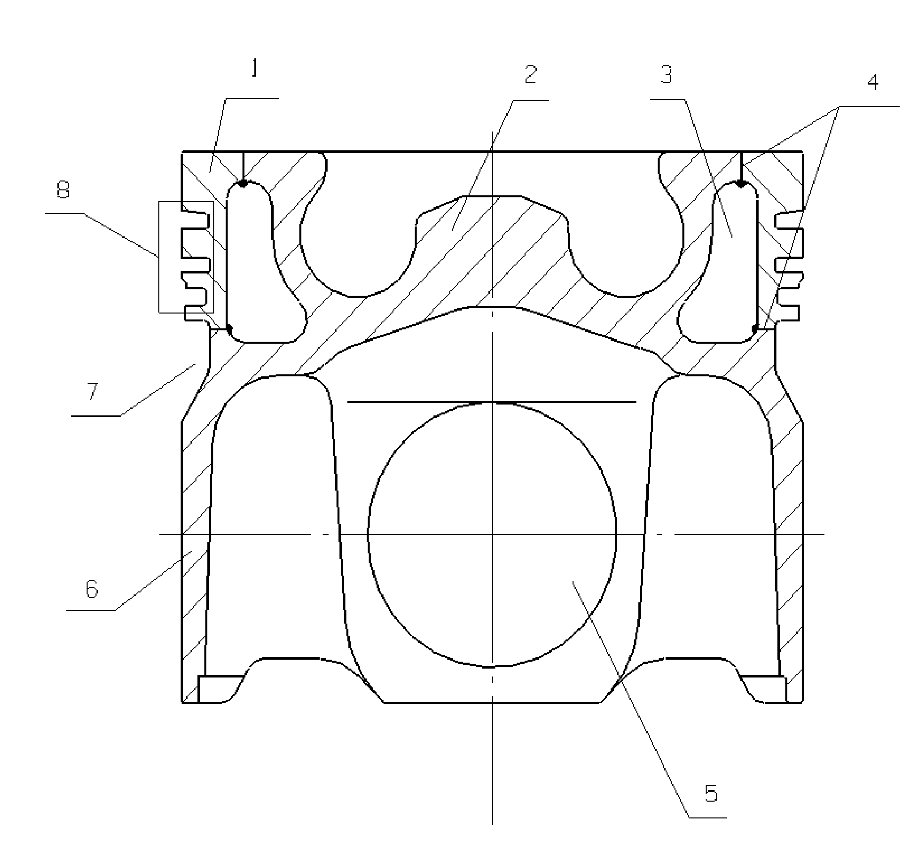
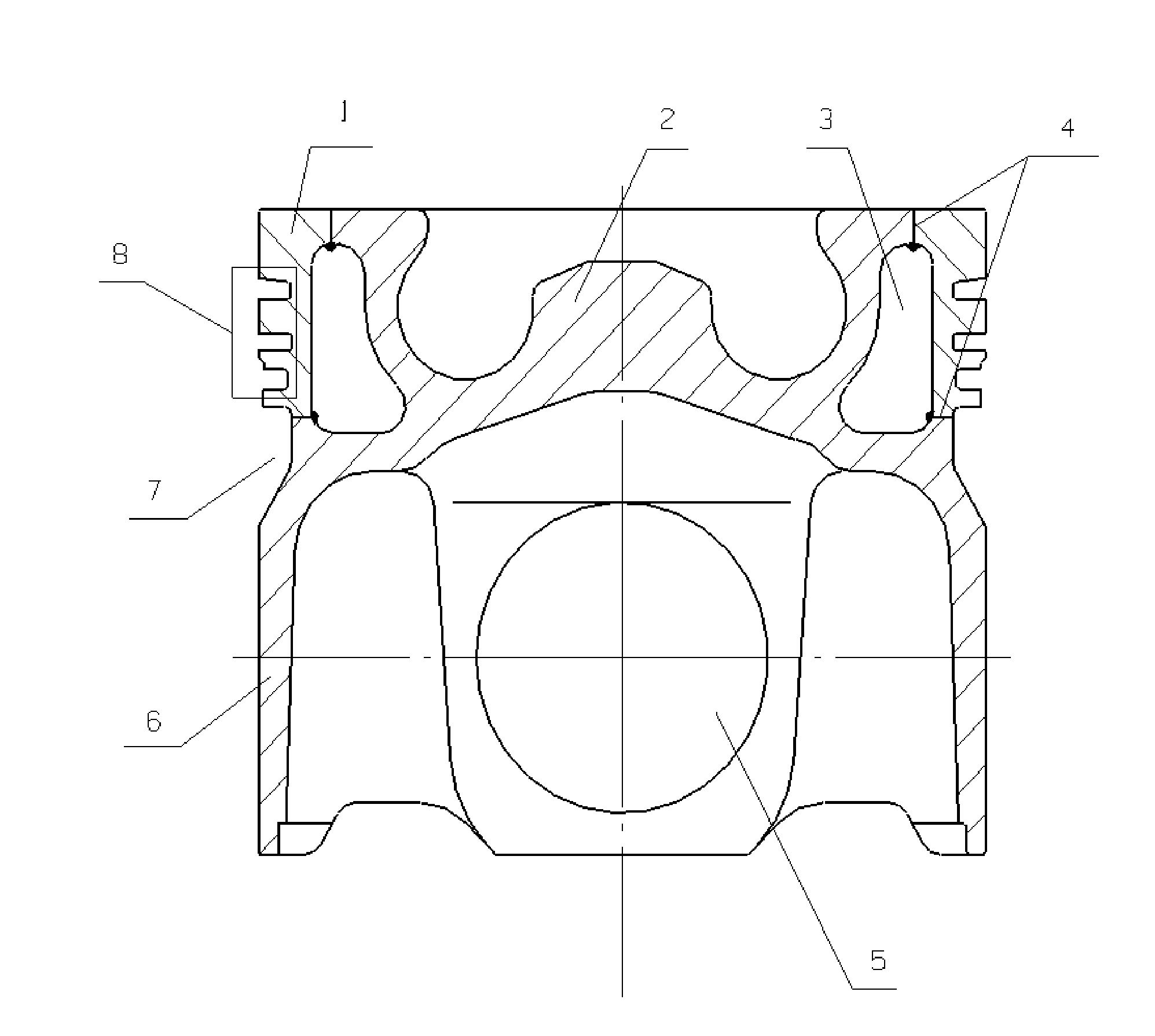
[0038]As shown in the FIGURE, the piston body member 2 and the piston ring member 1 are forged separately, and are welded together through laser welding procedure. One or more ring grooves 8 are formed on the outer surface of the piston ring member 1. The laser welding position 4 between the piston body member 2 and the piston ring member 1 are two ring-shaped welding lines on the top and side of the piston body member 2, respectively. An inner oil cooling chamber 3 is formed between the piston ring member 1 and the piston body member 2 after welding. The inner oil cooling chamber 3 is connected with the piston inner cavity by means of two or three oil inlet and outlet holes. A ring shaped groove 7 is processed at the skirt portion of the piston body member 2. A pin hole 5 is opened at the lower portion of the piston body member 2, and two recesses are processed at the two sides of the pin hole 5, respectively.

[0039]In accordance with the present invention, a manufacturing process f...

example 2

[0054]The structure of the piston in example 2 is the same as that of the piston in example 1. The manufacturing process comprises the steps of:[0055]1) forging separately the blank of piston body member and the blank of piston ring member;[0056]2) thermal-treating separately the blank of piston body member and the blank of piston ring member;[0057]3) sand blasting the blank of piston body member and the blank of piston ring member to manufacture the inner cavity, inner oil cooling chamber, and the laser welding surface;[0058]4) welding the piston body member and the piston ring member together through laser welding procedure;[0059]5) processing separately the piston ring shaped groove, combustion chamber, ring groove, pin hole, outer circle, and the oil inlet / outlet holes;[0060]6) phosphating or graphitizing the surface of the piston.

[0061]In accordance with the second example, the process for thermal treating quenched and tempered steel comprises holding the temperature at 800° C....

example 3

[0068]The structure of the piston in Example 3 is the same as that of the piston in Example 1, manufactured by the steps of:[0069]1) forging separately the blank of piston body member and the blank of piston ring member;[0070]2) thermally treating separately the blank of piston body member and the blank of piston ring member;[0071]3) sand blasting the blank of piston body member and the blank of piston ring member to manufacture the inner cavity, inner oil cooling chamber, and the laser welding surface;[0072]4) welding the piston body member and the piston ring member using a laser welding process;[0073]5) processing separately the piston ring shaped groove, combustion chamber, ring groove, pin hole, outer circle, and the oil inlet / outlet holes; and[0074]6) phosphating or graphitizing the surface of the piston.

[0075]In accordance with the third example of the invention, the process for thermal treating quenched and tempered steel comprises holding the temperature at 850° C. for 2 ho...


PUM

PropertyMeasurementUnit
Temperatureaaaaaaaaaa

Abstract

A laser-welded single-piece forged-steel piston with an enclosed inner oil cooling chamber having the advantages of simple structure and easy manufacturing process, and capable of satisfying the requirement of engines for high power, high rigidity, and low discharge development, and its manufacturing process. The laser-welded single-piece forged-steel piston of the invention comprises a piston body member and a piston ring member, wherein the piston body member is welded together with the piston ring member through laser welding procedure, an enclosed inner oil cooling chamber is formed between the piston body member and the piston ring member, and is connected with the piston inner cavity by means of at least two oil inlet / outlet holes, and a pin hole is opened at the lower portion of the piston body member.

Description

CROSS-REFERENCE TO RELATED APPLICATIONS[0001]This application claims priority benefits to Chinese Patent Application Number 200710015394.8 filed Jul. 20, 2007 and to Chinese Patent Application Number 200810099406.4 filed May 9, 2008. The contents of all of the aforementioned specifications are incorporated herein by reference.BACKGROUND OF THE INVENTION[0002]1. Field of the Invention[0003]The invention relates to a piston for an engine and to a method for manufacturing the same, and more particularly, to a laser-welded single-piece forged-steel piston with—inner oil cooling chamber and a method for manufacturing thereof.[0004]2. Description of the Related Art[0005]Currently, the development of engines for trucks, engineering machinery, locomotives, engine vessels, and so on, focuses on high power and heavy duty, resulting in higher requirements of rigidity and discharge levels. Although a conventional aluminum piston is light, it gradually fails to meet these demands. In diesel engi...

Claims


Application Information

Patent Timeline
IPC IPC(8): F16J1/00B23P15/10C21D1/58B23K26/20C21D9/00
CPCC21D1/58F02F3/003F02F3/22Y10T29/49249F02F2003/0061Y10T29/49265F02F2200/04
Inventor LIN, FENGHUAZHANG, QINGYUANMA, XUEJUNZHANG, FENG
Owner LIN FENGHUA
Learn More