
Load-minimizing, trolley arrester apparatus and method

a technology of arrester and trolley, which is applied in the direction of safety belts, rope railways, roads, etc., can solve problems such as hazards in wet conditions, and achieve the effect of significant adjustability

Inactive Publication Date: 2009-01-15
ZIPHLDG
View PDF16 Cites 22 Cited by
  • Summary
  • Abstract
  • Description
  • Claims
  • Application Information

AI Technical Summary

Benefits of technology

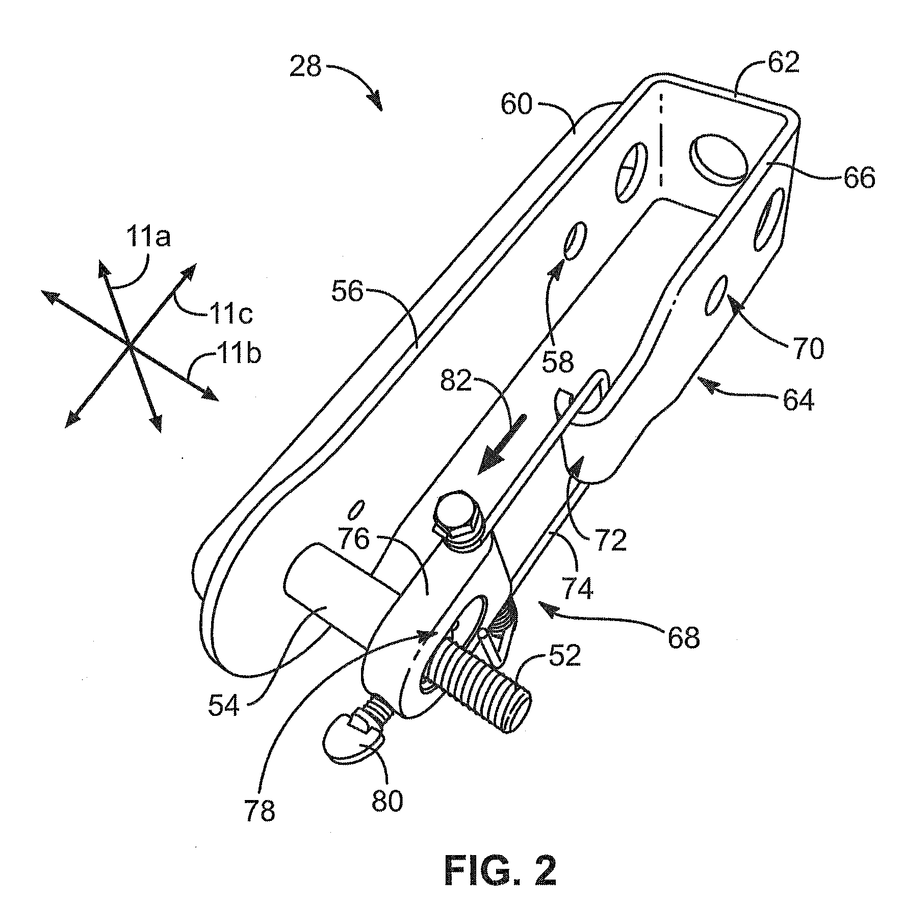
[0008]In view of the foregoing, in accordance with the invention as embodied and broadly described herein, a method and apparatus are disclosed in one embodiment of the present invention as including a trolley comprising a frame, a brake assembly, and a sheave mount. In selected embodiments, a brake assembly in accordance with the present invention may provide significant adjustability. For example, a brake assembly may include a brake pad that may be removed and replaced, should wear so dictate. Additionally, a brake pad may itself be readily adjustable to provide a desired or customized braking effect to suit conditions.

Problems solved by technology

Often a material that has certain advantageous characteristics may have others that are disadvantageous.
Accordingly, the material may be suitable for dry conditions, yet be hazardous for wet conditions.

Method used


Image

  • Load-minimizing, trolley arrester apparatus and method
  • Load-minimizing, trolley arrester apparatus and method
  • Load-minimizing, trolley arrester apparatus and method

Examples


Embodiment Construction

[0055]It will be readily understood that the components of the present invention, as generally described and illustrated in the drawings herein, could be arranged and designed in a wide variety of different configurations. Thus, the following more detailed description of the embodiments of the system and method of the present invention, as represented in the drawings, is not intended to limit the scope of the invention, as claimed, but is merely representative of various embodiments of the invention. The illustrated embodiments of the invention will be best understood by reference to the drawings, wherein like parts are designated by like numerals throughout.

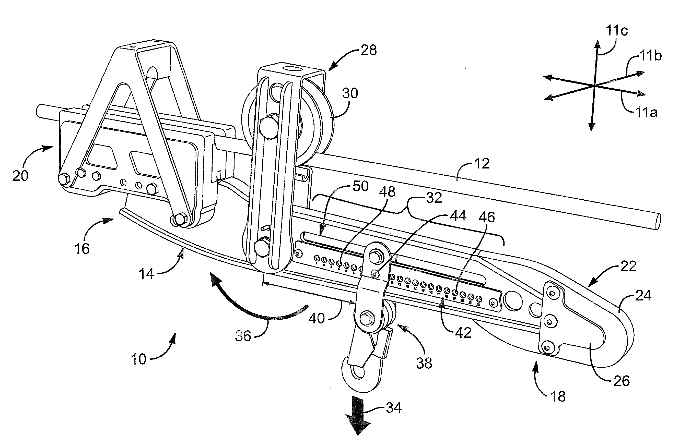
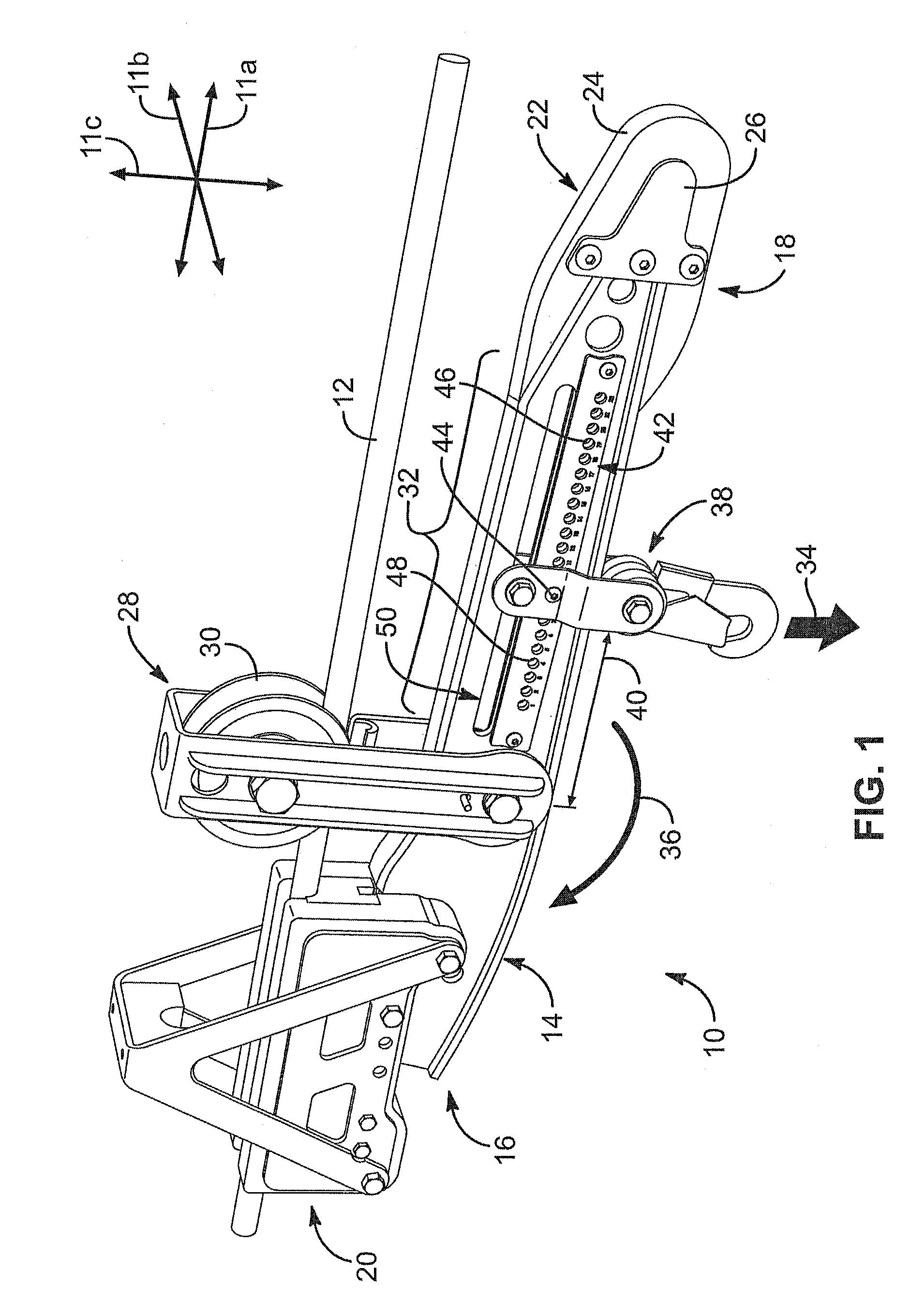
[0056]Referring to FIG. 1, in discussing a trolley 10 in accordance with the present invention, it may be advantageous to establish a coordinate system 11. Accordingly, a trolley 10 may be defined in terms of a longitudinal direction 11a, a lateral direction 11b, and a transverse direction 11c, substantially orthogonal to one an...


PUM


Abstract

A system comprising a cable held in suspension and a trolley traveling along the cable relies on a brake to control velocity and limit net downhill acceleration of the trolley. The trolley may include a brake pad positioned to contact the cable. At the downhill end of the ride, the lever actuating the brake is caught and lifted by a capture ring, thus relieving the braking load on the trolley. Also, the trolley engages a comparatively modest, second resistance mechanism, such as, for example, a system of springs, that gradually increases in resistance with distance of motion of the trolley thereagainst, bringing the trolley to a gradual halt at a rate to improve comfort of a rider and reduce acceleration forces (loads) on the trolley.

Description

RELATED APPLICATIONS[0001]This application is: (1) a continuation-in-part of co-pending U.S. patent application Ser. No. 11 / 605,853 filed on Nov. 28, 2006; and (2) a continuation-in-part of U.S. patent application Ser. No. 11 / 168,101 filed Jun. 28, 2005. Both U.S. application Ser. No. 11 / 605,853 and U.S. application Ser. No. 11 / 168,101 are hereby incorporated by reference.BACKGROUND[0002]1. The Field of the Invention[0003]This invention relates to suspended cable systems and, more particularly, to novel systems and methods for braking and retrieving trolleys traveling on suspended cable systems.[0004]2. The Background Art[0005]Weather conditions such as temperature and wetness affect the performance of typical trolleys configured to slide or roll along suspended cables. For example, rain on a cable may significantly change the coefficient of fiction between a trolley brake and the cable. Accordingly, a trolley brake that is acceptable for dry conditions, may be unacceptable for wet ...

Claims


Application Information

Patent Timeline
IPC IPC(8): B61B12/00B61B7/00
CPCA62B35/0093A63G21/22A63G21/20B61H9/02B61B7/02
Inventor CYLVICK, ERIC S.
Owner ZIPHLDG
Learn More