Slotted flow restrictor for a mass flow meter

a mass flow meter and restrictor technology, applied in the direction of volume/mass flow by dynamic fluid flow effect, measurement devices, instruments, etc., can solve the problems of interference with secondary flow and too much turbulence, and achieve the effect of infinite adjustmen

Inactive Publication Date: 2005-11-03
BROOKS INSTRUMENT
View PDF3 Cites 10 Cited by
  • Summary
  • Abstract
  • Description
  • Claims
  • Application Information

AI Technical Summary

Benefits of technology

[0006] A flow restrictor can enable nearly infinite adjustability for the conductance of fluids within a range of physical displacements that correlate to measurable pressure drops. The restrictor may be constructed of a solid material in which slots originate from the outer surface of the material and progress inward. The flow restrictor can be manufactured and integrated into equipment without the need of significant changes to the other parts of the equipment.

Problems solved by technology

A solid restrictor may not allow enough fluid to flow through the primary flow path or may cause too much turbulence just upstream of the flow restrictor, downstream, or both.
This can interfere with the fluid flowing through the secondary flow path having the sensor.
Further, the shape of the slots 22 may be a function of pressure during an insertion operation and may be undesired.

Method used


Image

  • Slotted flow restrictor for a mass flow meter
  • Slotted flow restrictor for a mass flow meter
  • Slotted flow restrictor for a mass flow meter

Examples


example

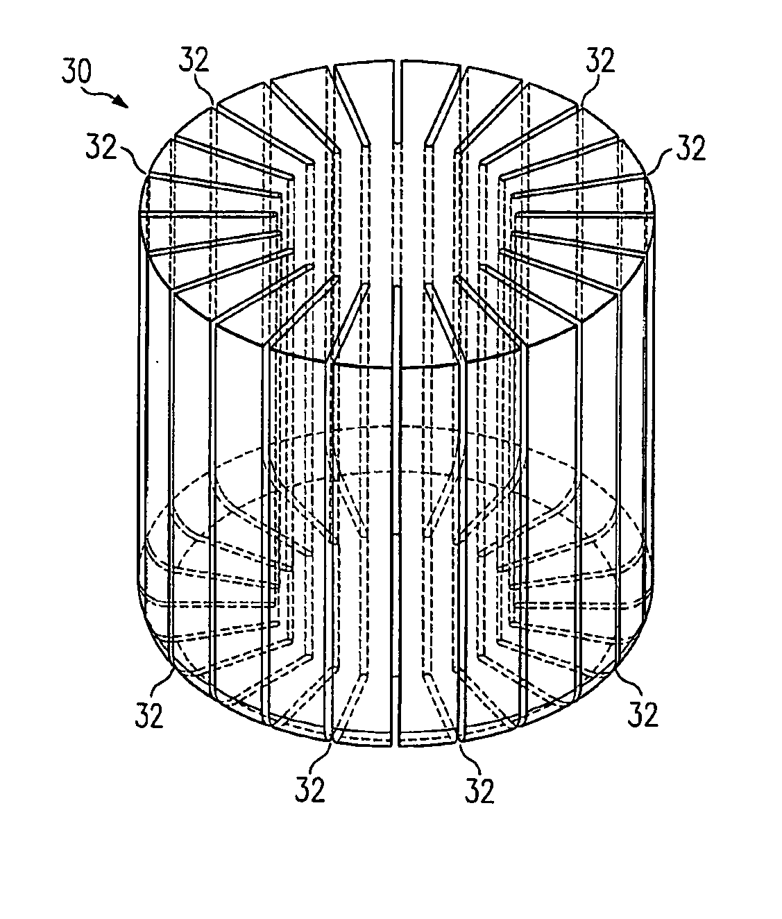
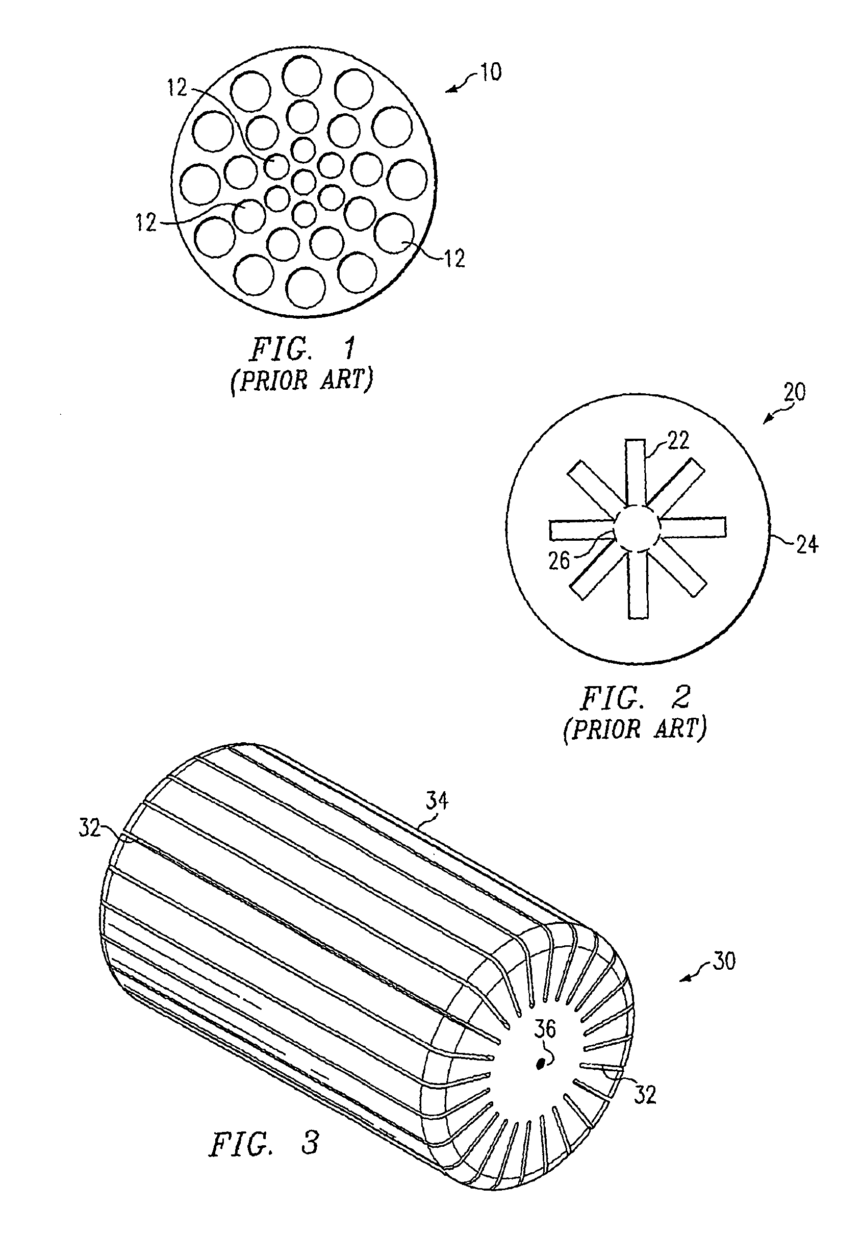
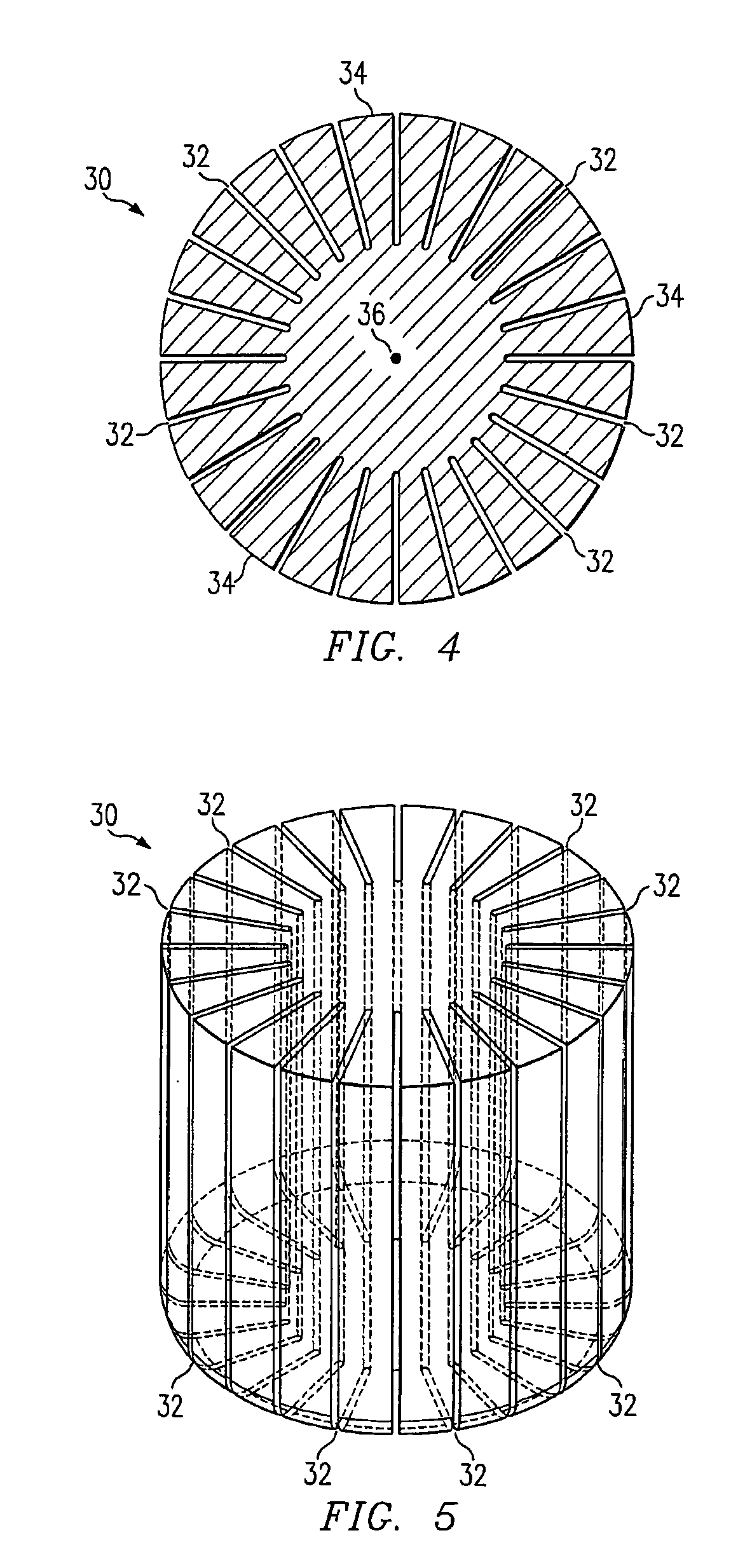
[0038] A specific non-limiting example is given to illustrate some dimensions and design considerations. A mass flow controller has a nominal flow rating of 30 standard liters per minute for nitrogen (N2) gas. The flow restrictor may have an overall length of approximately 19 millimeters and a larger width of approximately 9.8 millimeters. The taper is approximately 2 degrees overall. The flow restrictor can have 24 slots with each slot having a depth of approximately 3200 microns and width of approximately 250 microns. The aspect ratios for the slots are approximately 13:1. Wires may be attached to the flow restrictor, and each wire may have a diameter of approximately 200 microns. After preparing the restrictor and wires, the combination may be inserted into the mass flow controller. The rest of the fabrication and calibration of the mass flow controller can be performed using a conventional method.

[0039] The flow restrictor 30 may be used in nearly any flow apparatus including a...


PUM


Abstract

A flow restrictor (30) for a mass flow metering device formed of a solid material and slots (32) originating from an outer surface towards inward.

Description

FIELD OF THE INVENTION [0001] This invention relates in general to flow restrictors and apparatuses including flow restrictors, and more particularly, to flow restrictors having slots and apparatuses having those flow restrictors and method of forming and using the flow restrictors and apparatuses. DESCRIPTION OF THE RELATED ART [0002] Mass flow controllers that operate on heat transfer principles have been widely adopted. The mass flow controllers typically have a small diameter tube (for sensing) in parallel with a primary flow path through the controller. Typically, a partial fluid flow blockage along the primary flow path is used to divert some of the fluid flow to the secondary flow path where sensing may occur. [0003] One attempt to address the flow diversion is to use a flow restrictor within a primary flow path. The flow restrictor may be generally cylindrical with a slight taper that may reside within a tube having a similar taper. The flow restrictor may be held in positio...

Claims


Application Information

Patent Timeline
Patent Type & Authority Applications(United States)
IPC IPC(8): F15D1/02G01F1/00G01F1/22G01F1/40G01F1/42G01F1/48
CPCG01F1/42G01F1/40
Inventor TISON, STUART A.WU, GUANGHUAGILL, TRACYLOPEZ, VINCENT
Owner BROOKS INSTRUMENT
Why Eureka
Try Eureka