
Saw and drill machine for paved slabs

a technology of paved slabs and drills, which is applied in cutting machines, roads, construction, etc., can solve the problems of limiting the time required to make saw cuts around and drill holes in the section of concrete to be removed, and freeze further expanding defects, etc., to achieve the effect of convenient transportation

Active Publication Date: 2014-09-18
KNAPP RONALD A
View PDF13 Cites 9 Cited by
  • Summary
  • Abstract
  • Description
  • Claims
  • Application Information

AI Technical Summary

Benefits of technology

The sawing and drilling machine described in the patent has a drill attached to a telescoping arm and leg that can be rotated and adjusted to create holes in a paved slab. The machine also has a rear frame for supporting a hydraulic fluid reservoir and power unit, as well as coolant tanks and an air compressor. The front frame can support a trailer for transport to a work site, and the telescoping legs of the center frame can be extended to support the weight of the trailer and lift the weight off of the trailer support wheels. The technical effect of this machine is that it allows for efficient and accurate drilling and cutting of holes in a paved slab, and facilitates transport and installation in a compact and easy-to-use way.

Problems solved by technology

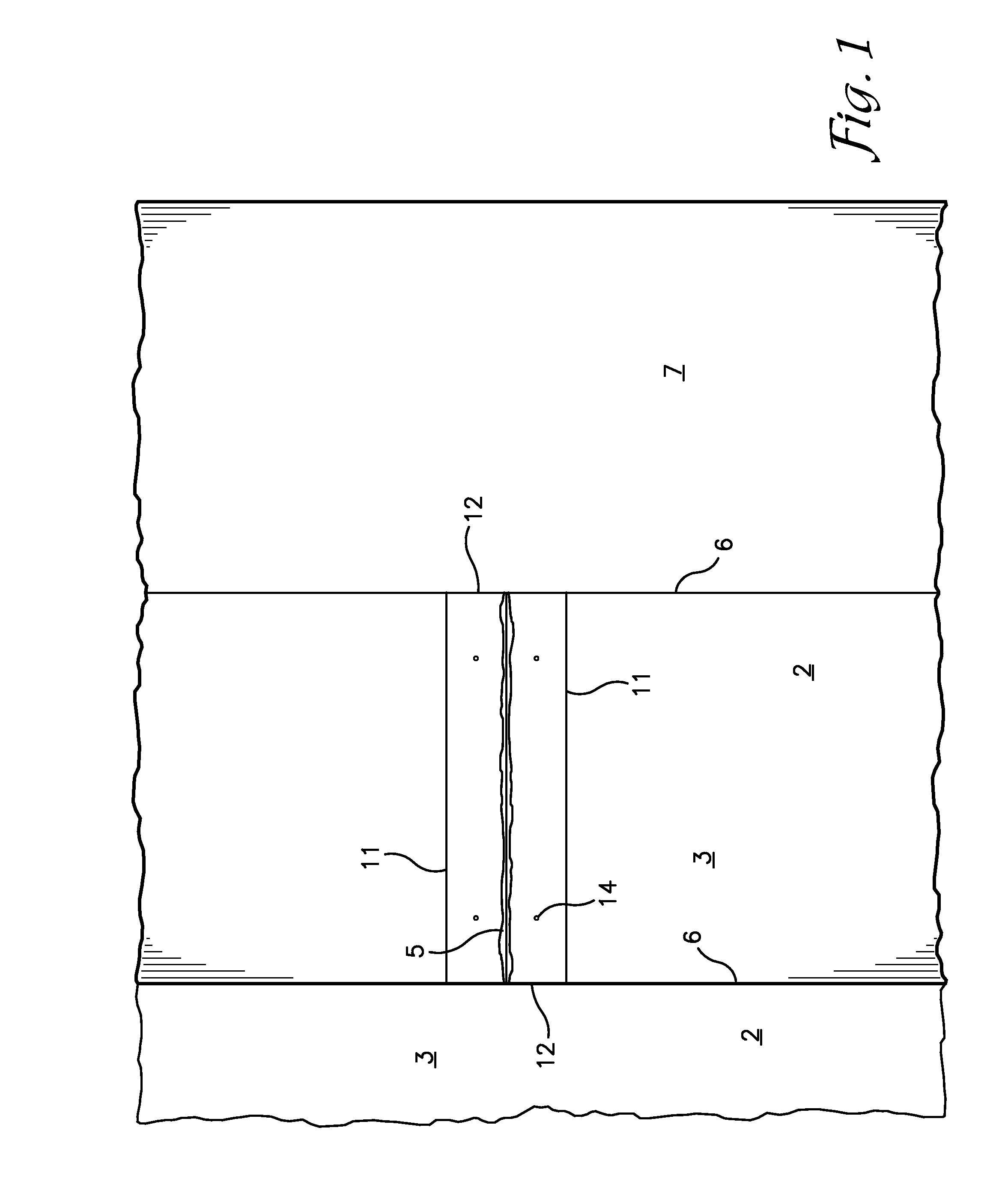
Damage at the lateral control joints 5, typically starts with chipping and spawling of the edges of the joint 5, forming a small depression which then grows as tires continuously pound against the defect and water seeps into the cracks therein and freezes further expanding the defects.
The time required to make the saw cuts around and drill the holes in the section of the concrete slab to be removed is a significant limiting factor as to the number of fragmented slab sections that can be removed in the time allotted.

Method used


Image

  • Saw and drill machine for paved slabs
  • Saw and drill machine for paved slabs
  • Saw and drill machine for paved slabs

Examples


Embodiment Construction

[0036]As required, detailed embodiments of the present invention are disclosed herein; however, it is to be understood that the disclosed embodiments are merely exemplary of the invention, which may be embodied in various forms. Therefore, specific structural and functional details disclosed herein are not to be interpreted as limiting, but merely as a basis for the claims and as a representative basis for teaching one skilled in the art to variously employ the present invention in virtually any appropriately detailed structure. The drawings constitute a part of this specification and include exemplary embodiments of the present invention and illustrate various objects and features thereof.

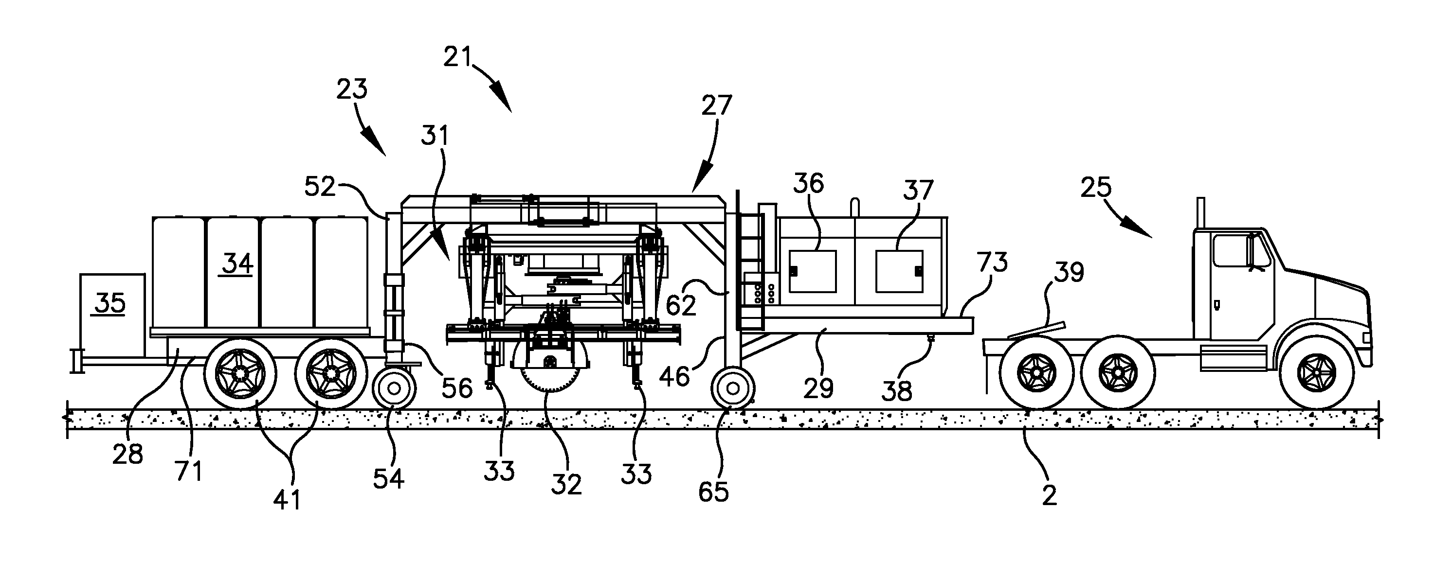
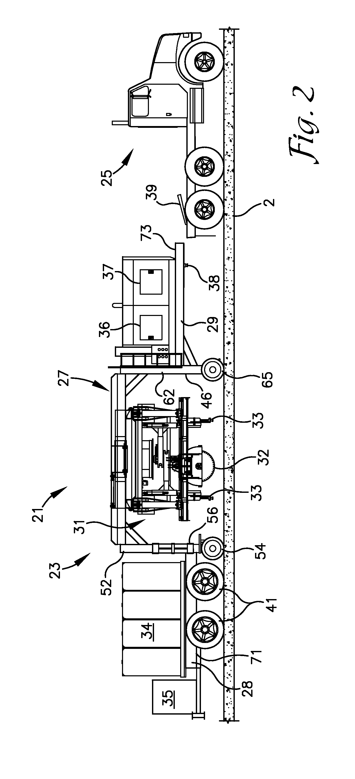
[0037]With initial reference to FIG. 2, the reference number 21 generally designates a mobile saw and drilling machine for making cuts through and boring holes into a section of a slab to be removed from a lane 3 of a road. When describing the mobile saw and drill 21 herein, directional references...


PUM

PropertyMeasurementUnit
Angleaaaaaaaaaa
Angleaaaaaaaaaa
Angleaaaaaaaaaa

Abstract

A machine for making cuts through and boring holes into a paved slab includes a pair of saw guide tracks with circular saws mounted thereon for linear movement in parallel spaced relationship. The tracks and saws are mounted on a laterally expandable support frame which is rotatably suspended from a main frame for adjusting the spacing between cuts. The saw guide tracks are suspended from the laterally expandable saw and track support frame by vertically telescoping legs operable to raise and lower the guide tracks and saws supported thereon relative to the paved slab. Drills are mounted on a drill support assembly that telescopes laterally and vertically and which is rotatable about a vertical axis to permit adjustment to the positioning of the drills for boring holes in the slab.

Description

CROSS-REFERENCE TO RELATED APPLICATIONS[0001]This application claims priority from U.S. Provisional Patent Application No. 61 / 780,055 filed Mar. 13, 2013, the disclosure of which is hereby incorporated herein, in its entirety, by reference.BACKGROUND OF THE INVENTION[0002]1. Field of the Invention[0003]The present invention is directed to a machine for making saw cuts and drilling holes into a paved slab.[0004]2. Background of the Invention[0005]With reference to the section of road 1 as shown in FIG. 1, a common practice for repairing damaged sections of concrete slabs 2 forming the lanes 3 of a road is to cut out and remove a damaged section and pour and finish a concrete patch in the remaining hole. The area around lateral control joints 5 formed in the slabs 2 which have degraded over time are areas that are commonly in need of repair. The concrete slab 2 forming a road is typically poured as a generally continuous slab. The slab may be approximately nine to twelve inches thick....

Claims


Application Information

Patent Timeline
IPC IPC(8): E01C23/09
CPCE01C23/094E01C23/0933B28D1/045E01C19/004
Inventor KNAPP, RONALD A.
Owner KNAPP RONALD A
Learn More