Device for Manufacturing Sheet Glass and Method for Manufacturing Sheet Glass

a technology of sheet glass and manufacturing method, which is applied in the direction of glass making apparatus, glass rolling apparatus, manufacturing tools, etc., can solve the problems of reduced quality or yield of sheet glass, and inability to eliminate the significant so as to improve the quality or production yield of the sheet glass, the effect of significant reduction of the reduction or stop of the flow speed of the molten glass and the reduction of the total

Active Publication Date: 2009-01-15
NIPPON ELECTRIC GLASS CO LTD
View PDF4 Cites 12 Cited by
  • Summary
  • Abstract
  • Description
  • Claims
  • Application Information

AI Technical Summary

Benefits of technology

[0009]The generation of such event causes the molten glass G1 of which flow speed is reduced or stopped to be subjected to devitrification and the devitrification leaves defects in the sheet glass 23, leading to the reduction in quality of the sheet glass 23 and thus the reduction in production yield. In addition, since the inner surface of the large diameter tube 72c (as well as the inner surface of the small diameter tube 72a) is generally formed with platinum, a contact time between the molten glass G1 and the platinum becomes inappropriately longer when the molten glass G1 is stopped. This causes blister to be easily generated at a platinum interface and generates a concern of including bubbles in the sheet glass. This also leads to the reduction in quality or yield of the sheet glass 23.
[0028]As described above, according to the present invention, during the process in which the molten glass flows from the small diameter tube portion to the large diameter tube portion through the expanded diameter tube portion, the flow that gradually expands while moving downstream is generated as a flow of the molten glass. Since the flow is along the inner surface of the expanded diameter tube portion, the partial reduction or stop of the flow speed of the molten glass can be suppressed. Accordingly, the likelihood of devitrification or bubble generation due to the reduction or stop of the flow speed of the molten glass is significantly reduced, and the improvement of quality or production yield of the sheet glass can be achieved. In addition, when the small diameter tube portion, the expanded diameter tube portion, and the large diameter tube portion are integrally and continuously connected to one another, the resistance which is applied to the molten glass from the tube during the movement is larger in the small diameter tube portion provided at the upstream and is smaller in the large diameter tube portion provided at the downstream, and thus the flow rate of the molten glass supplied to the forming vessel in the forming furnace is controlled by the viscosity of the molten glass in the small diameter tube portion. Therefore, the effect of temperature change on the flow rate near the forming furnace is small. As a result, even when the thickness distribution or the like of the sheet glass is changed, the flow rate of the molten glass supplied to the forming vessel in the forming furnace is prevented from being rapidly changed.

Problems solved by technology

This causes blister to be easily generated at a platinum interface and generates a concern of including bubbles in the sheet glass.
This also leads to the reduction in quality or yield of the sheet glass 23.
Taking into consideration the fact that the fluid level L of the molten glass in the upstream end portion of the large diameter tube 72c moves up and down as described above, such arrangement is significantly difficult, leading to the problems generated by inability of complete elimination of the significant reduction or stop of the flow speed of the molten glass G1 as described above.
In addition, since bubbles are generated due to the inclusion of an atmospheric gas at the lower end of the small diameter tube 72a, the reduction in the quality or the production yield of sheet glass becomes a concern.
The aforementioned problems may also arise when the sheet glass is formed by not only the overflow down-draw process but also the slot down-draw process.

Method used


Image

  • Device for Manufacturing Sheet Glass and Method for Manufacturing Sheet Glass
  • Device for Manufacturing Sheet Glass and Method for Manufacturing Sheet Glass
  • Device for Manufacturing Sheet Glass and Method for Manufacturing Sheet Glass

Examples


first embodiment

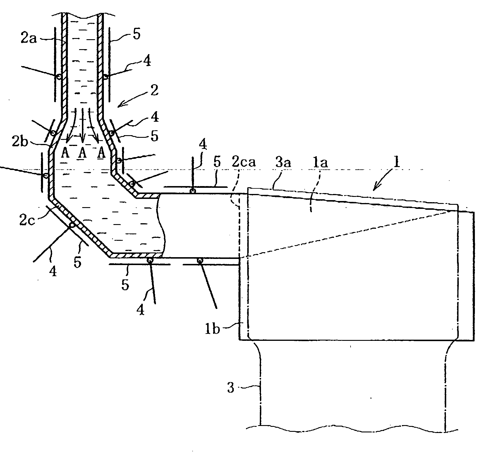
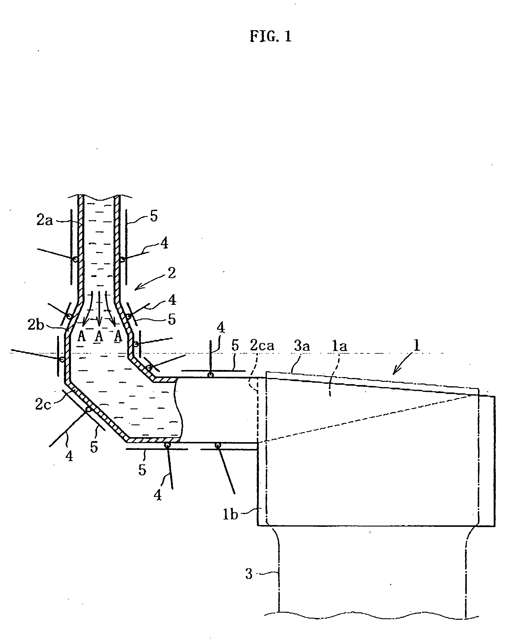
[0047]First, a device for manufacturing sheet glass according to the present invention will be described with reference to FIG. 1. A supplying tube 2 connected to a forming vessel (a groove-shaped overflow vessel) 1a in a forming furnace 1 shown in the figure is provided in a downstream end portion of a supplying passage (all supplying passages) of a molten glass from a melting furnace (not shown) to the overflow vessel 1a. The supplying tube 2 is composed of: a small diameter tube portion 2a of which upstream end is connected to, for example, a vessel (not shown) for soaking the molten glass and which has a small flow passage area; an expanded diameter tube portion 2b which is integrally and continuously connected to the downstream end of the small diameter tube portion 2a and of which flow passage area (tube diameter) gradually expands toward the downstream; and a large diameter tube portion 2c which is integrally connected to the downstream end of the expanded diameter tube porti...

third embodiment

[0054]In the present invention shown in FIG. 3a, a supplying tube 22 is divided into a small diameter tube portion 22a having a substantially constant diameter, and an expanded diameter tube portion 22b and a large diameter tube portion 22c which are integrally and continuously connected to each other, and a downstream end portion of the small diameter tube portion 22a is inserted into an upstream end portion of the expanded diameter tube portion 22b to be overlapped with each other. Even with such structure, it is possible to suppress a rapid change of the flow rate of the molten glass supplied from the downstream end of the large diameter tube portion 22c to the overflow vessel in the forming furnace, and sufficiently suppress the devitrification or the bubble generation caused by the partial reduction in flow speed or stoppage of the molten glass, as compared with the conventional art.

[0055]In a fourth embodiment of the present invention shown in FIG. 3b, a supplying tube 32 is d...


PUM

PropertyMeasurementUnit
Temperatureaaaaaaaaaa
Flow rateaaaaaaaaaa
Diameteraaaaaaaaaa

Abstract

A supplying tube 2 of a molten glass, which is placed in a downstream end portion of a supplying passage directing the molten glass flowing out of a melting furnace to a forming vessel 1a in a forming furnace 1, has a small diameter tube portion 2a which has a small flow passage area and is provided at an upstream side, and a large diameter tube portion 2c which is provided at a downstream side of the small diameter tube portion 2a and has a large flow passage area. An expanded diameter tube portion 2b of which flow passage area gradually expands toward the downstream side is interposed between the small diameter tube portion 2a and the large diameter tube portion 2c. The small diameter tube portion 2a, the expanded diameter tube portion 2b, and the large diameter tube portion 2c may be integrally and continuously connected to one another.

Description

FIELD OF THE INVENTION[0001]The present invention relates to a device and a method for manufacturing sheet glass. In particular, the present invention relates to a technique of appropriately supplying molten glass to a forming vessel in a forming furnace when a sheet glass is continuously formed from the molten glass within the forming furnace.BACKGROUND OF THE INVENTION[0002]In general, a down-draw process and an up-draw process are known as methods for continuously forming, from molten glass, a sheet glass used in the manufacture of a flat display or the like such as by liquid crystal display. The down-draw process is basically classified into an overflow down-draw process and a slot down-draw process.[0003]As an example, means for manufacturing sheet glass by the overflow down-draw process will be described. The temperature of molten glass obtained by heating a glass raw material in a melting furnace is reduced until the molten glass has a viscosity suitable for the formation. Th...

Claims


Application Information

Patent Timeline
IPC IPC(8): C03B18/02C03B5/16
CPCC03B17/064C03B7/02Y02P40/57C03B17/06
Inventor KANO, TOMONORI
Owner NIPPON ELECTRIC GLASS CO LTD
Why Eureka
Try Eureka