
Short length compliant pin, particularly suitable with backplane connectors

Active Publication Date: 2009-01-08
MOLEX INC
View PDF8 Cites 28 Cited by
  • Summary
  • Abstract
  • Description
  • Claims
  • Application Information

AI Technical Summary

Benefits of technology

[0009]It is therefore a general object of the present invention to provide an improved connector for high speed data transmission which has reduced crosstalk and which operates reliably at high speeds.
[0015]The connectors are provided with reduced length compliant mounting pins. The reduced length of these pins permits them to be arranged and fit within an envelope of space defined by an imaginary datum line drawn from a front edge of the daughter card connector and generally parallel to the base spoke member of the connector units. The reduce length of the mounting pins also permits a greater extent of back drilling to be performed on the daughter card circuit board. The reduced length of the shortened compliment pins of the present invention and consequential potential for reduced via length with appropriate backdrilling can reduce electrical stub length and improve high speed performance of the connectors upon which the novel compliant pins are used, whether the connectors be backplane connectors or input / output connectors or any other connector which are desired for high speed applications.
[0016]With the compliant pins of the present invention, a reduction in force needed to apply the connectors to their mounting circuit boards is obtained. The benefits of backdrilling are obtained and backdrilling is made easier. Further, increased electrical performance is obtained.

Problems solved by technology

As signal terminal are positioned closer together, signal interference occurs between closely spaced signal terminals especially between pairs of adjacent differential signal terminals.
This affects signal integrity of the entire signal transmission system.
These shields add significant cost to the connector and also increase the size of the connector.
However, the use of ground terminals the same size as the signal terminals leads to problems in coupling which may drive up the system impedance.
It becomes difficult to match the impedance within the body of the connector and along the body portions of the terminals in that the terminal body portions have different configurations and spacing than do the contact portions of the terminals.
Large press-in forces may inadvertently lead to damage of the terminal tails or other parts of the connector.

Method used


Image

  • Short length compliant pin, particularly suitable with backplane connectors
  • Short length compliant pin, particularly suitable with backplane connectors
  • Short length compliant pin, particularly suitable with backplane connectors

Examples


Embodiment Construction

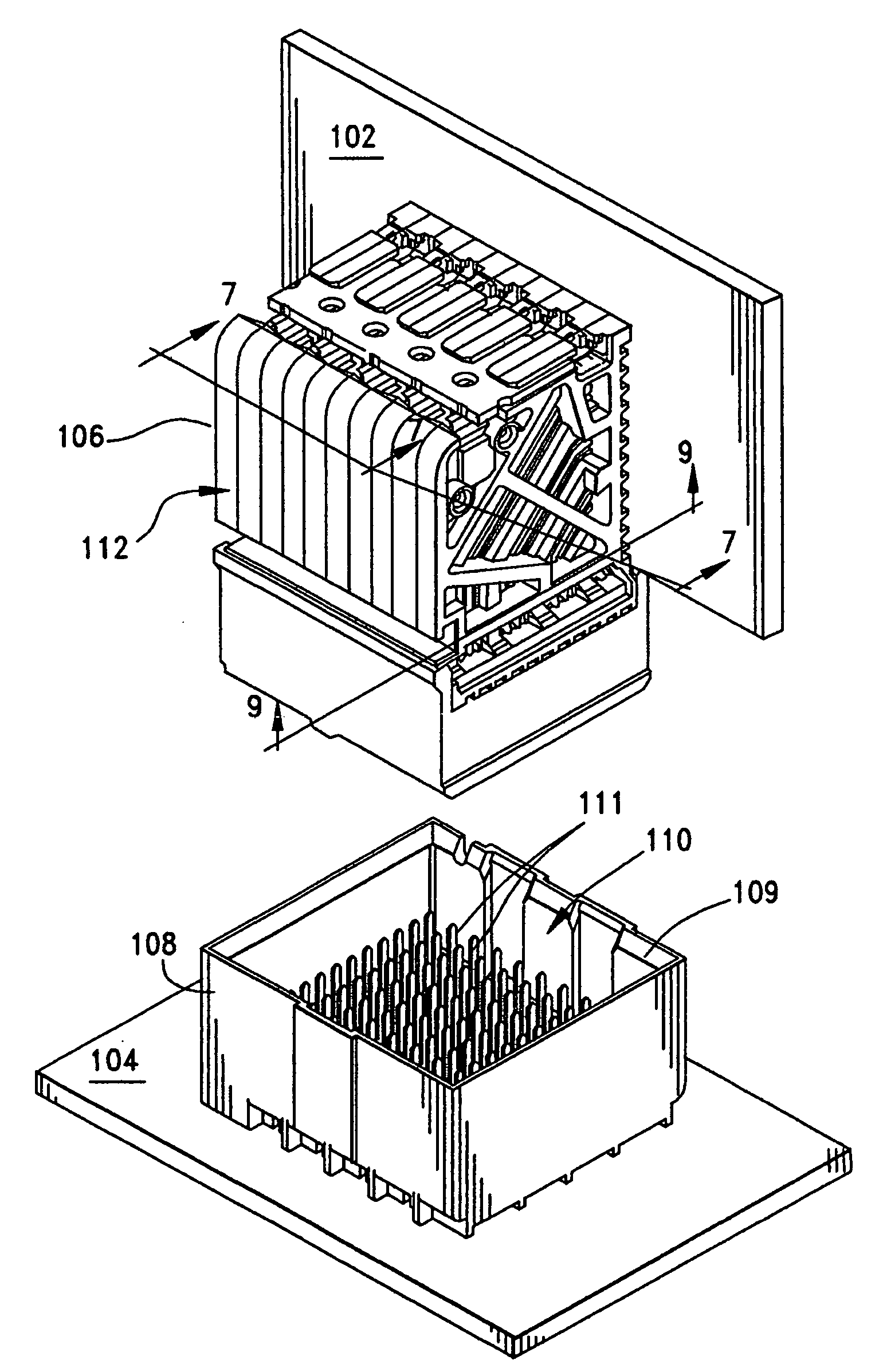
[0032]FIG. 1 illustrates a backplane connector assembly 100 that is constructed in accordance with the principles of the present invention and which is used to join an auxiliary circuit board 102, known in the art as a daughter card, to another circuit board 104, typically referred to in the art as a backplane. The assembly 100 includes two connectors 106 and 108. As shown best in FIG. 2, the backplane connector 108 takes the form of a pin header having an four sidewalls 109 that cooperatively define a hollow receptacle 110. A plurality of conductive terminals in the form of pins 111 are provided and held in corresponding terminal-receiving cavities of the connector 108 (not shown). The pins 111 are terminated, such as by tail portions to conductive traces on the backplane 104 and these tail portions fit into plated vias, or through holes disposed in the backplane.

[0033]Turning to FIG. 3, the daughter card connector 106 is composed of a plurality of discrete connector units 112 that...


PUM


Abstract

An electrical connector having a plurality of connector units each having a pair of columns of edge coupled differential signal pairs separated by a ground shield terminal. The ground shield terminals each face a different signal pair of terminals in an adjacent column. Notwithstanding the different size and configurations of the ground and signal terminals, the terminals have mounting tail portions that are disposed in a uniform array different from the arrangement of the body portions of the terminals of the connector unit. The mounting tail portions are of a reduced length which benefit the electrical performance of the connector where it meets its supporting circuit board.

Description

REFERENCE TO RELATED APPLICATIONS[0001]This application claims the domestic benefit of U.S. Provisional Application Nos. 60 / 936,374, filed on Jun. 20, 2007, the disclosure of which is herein incorporated by reference.BACKGROUND OF THE INVENTION[0002]The present invention relates generally to high speed connectors, and more particularly to high speed backplane connectors, with reduced crosstalk and improved performance.[0003]High speed connectors are used in many data transmission applications particularly in the telecommunications industry. Signal integrity is an important concern in the area of high speed and data transmission for components need to reliably transmit data signals. The high speed data transmission market has also been driving toward reduced size components and increased signal density.[0004]High speed data transmission is utilized in telecommunications to transmit data received from a data storage reservoir or a component transmitter and such transmission most commo...

Claims


Application Information

Patent Timeline
IPC IPC(8): H01R13/648
CPCH01R12/585H01R12/716H01R12/737H01R23/6873H01R12/724H01R13/658
Inventor AMLESHI, PEEROUZLAURX, JOHNBRUNKER, DAVIDREGNIER, KENT
Owner MOLEX INC
Learn More