
Light source device, display apparatus, and optical member

a technology of light source device and optical member, which is applied in the direction of lighting and heating apparatus, display means, instruments, etc., can solve the problems of reducing light utilization efficiency, affecting the efficiency of light utilization, so as to achieve high light utilization efficiency, reduce the amount of light loss through the edges of the optical sheet, and high reflectivity

Active Publication Date: 2009-01-08
SATURN LICENSING LLC
View PDF11 Cites 11 Cited by
  • Summary
  • Abstract
  • Description
  • Claims
  • Application Information

AI Technical Summary

Benefits of technology

The present invention provides a light source device, display apparatus, and optical member that can enhance the brightness and reduce non-uniformity in brightness, by improving the efficiency of light utilization. This is achieved by using an optical member with higher reflectivity than the support portion, which reduces the amount of light loss through the edges of the optical sheet and allows for higher light utilization efficiency.

Problems solved by technology

However, since components with a low reflectivity (of about 50%), such as a middle chassis, are disposed near a side surface and peripheral region of the optical sheet, a portion of the light emitted from the light-emitting unit leaks through these components so as to undesirably become absorbed.
This results in reduced light utilization efficiency.
This leads to non-uniformity in brightness (creates variation in brightness), resulting in lower display quality.

Method used


Image

  • Light source device, display apparatus, and optical member
  • Light source device, display apparatus, and optical member
  • Light source device, display apparatus, and optical member

Examples


Embodiment Construction

[0021]Embodiments of the present invention will now be described with reference to the drawings.

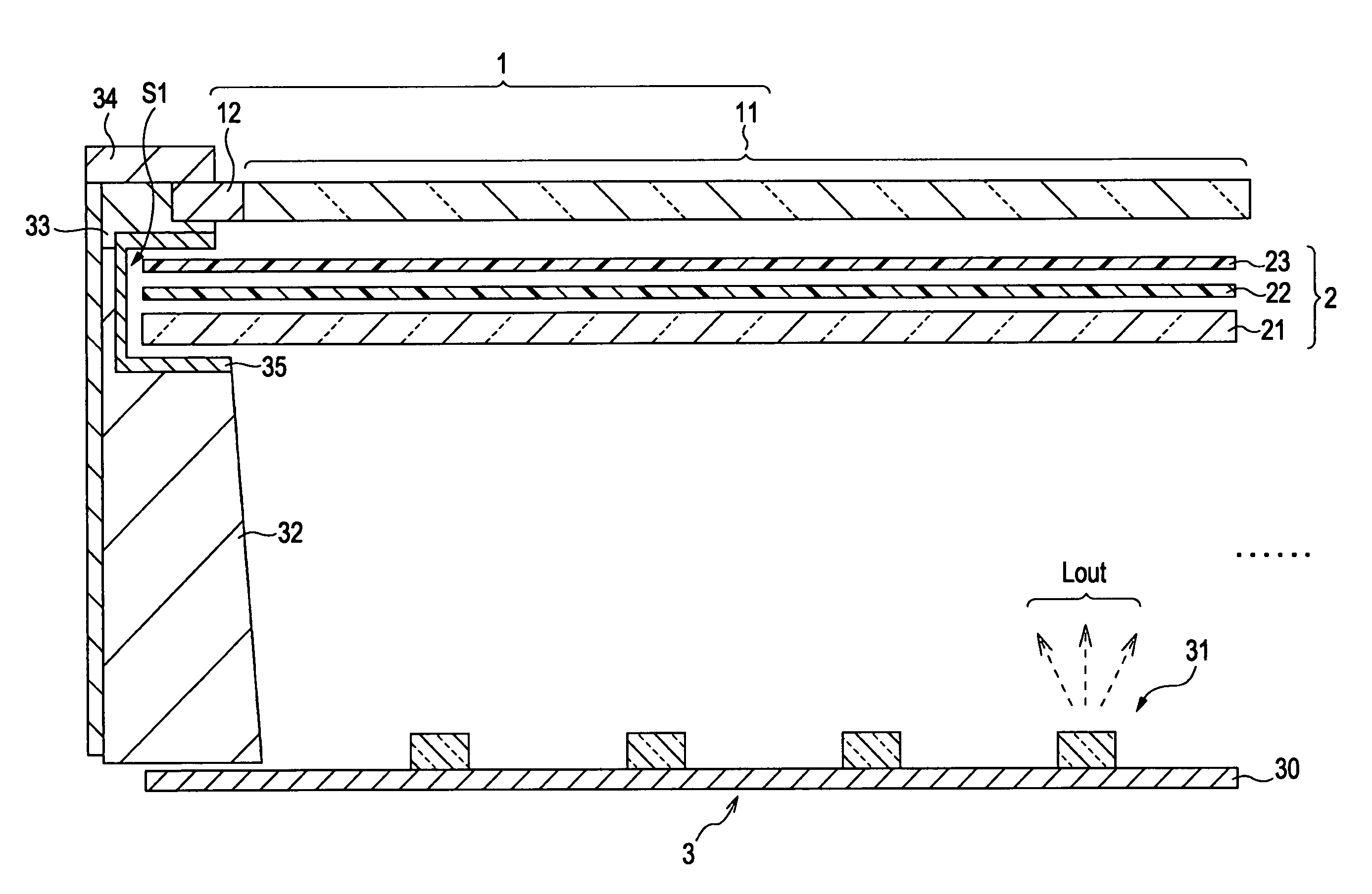
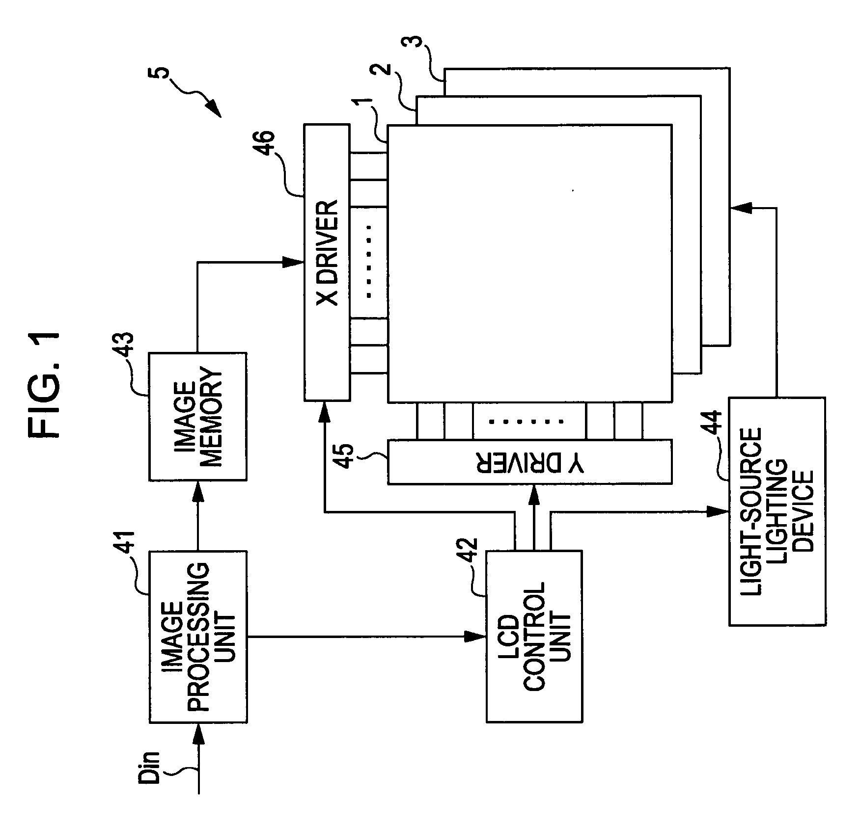
[0022]FIG. 1 is a block diagram of an entire display apparatus (liquid crystal display apparatus 5) equipped with a light source device (light source device 3) according to an embodiment of the present invention. The liquid crystal display apparatus 5 includes a liquid crystal display (LCD) panel 1, an optical sheet 2, the light source device 3, an image processing unit 41 that performs signal processing on an input image signal Din, an LCD control unit 42 that controls, for example, the LCD panel 1, an image memory 43 that stores an image signal, a light-source lighting device 44 that controls the lighting operation of the light source device 3, and a Y driver (gate driver) 45 and an X driver (data driver) 46 that drive the LCD panel 1.

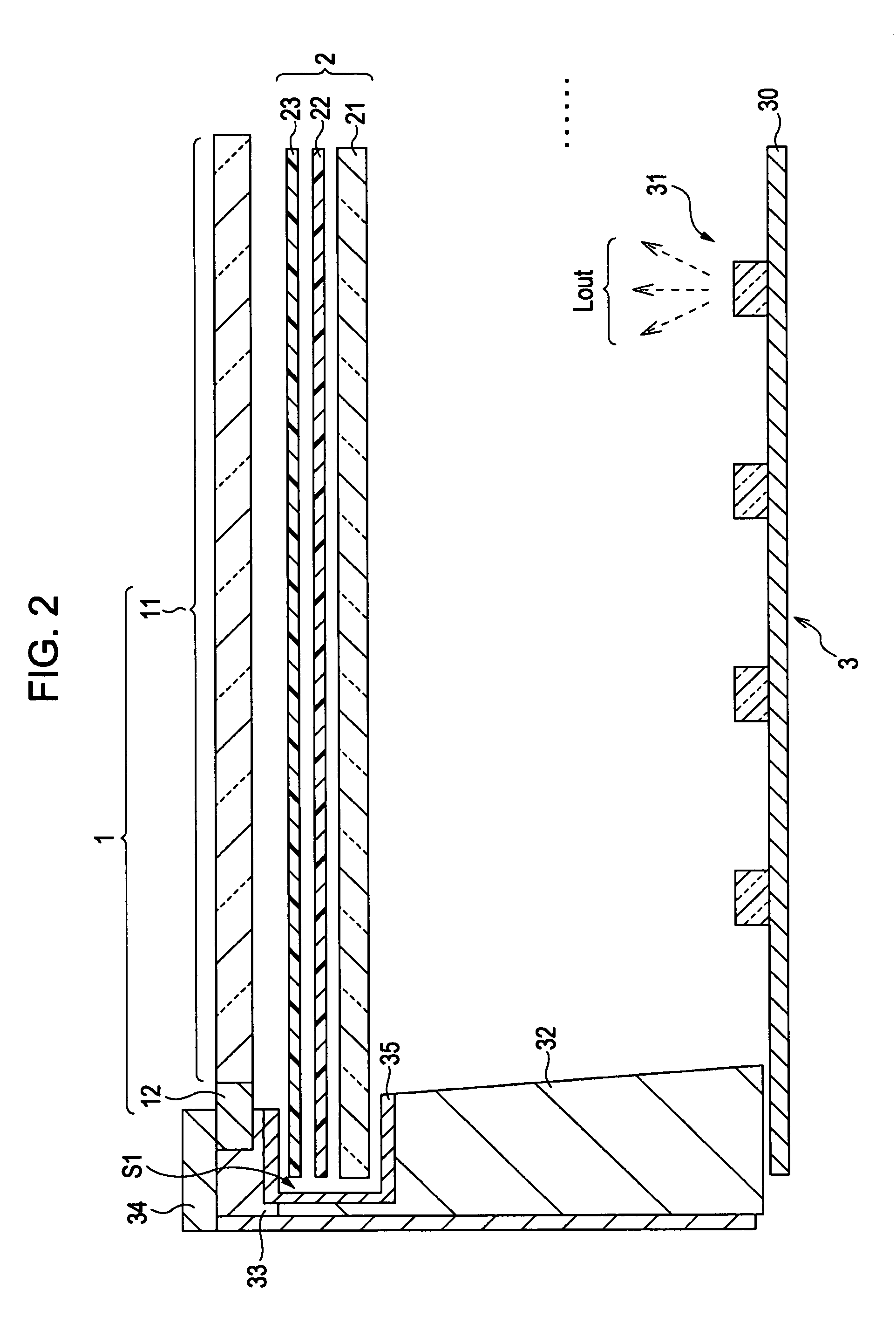
[0023]FIG. 2 is a cross-sectional view showing a relevant part of the liquid crystal display apparatus 5 (specifically, the LCD panel 1, the optical sheet...


PUM


Abstract

An optical member is disposed between an optical sheet and a pair of middle chassis and top chassis that securely support an edge of an liquid crystal panel and an edge of the optical sheet. The optical member reflects light emitted from light-emitting diodes at high reflectivity so that an amount of light loss through the edge of the optical sheet is reduced. This allows for higher light utilization efficiency, thereby enhancing the brightness.

Description

CROSS REFERENCES TO RELATED APPLICATIONS[0001]The present invention contains subject matter related to Japanese Patent Application JP 2007-174871 filed in the Japanese Patent Office on Jul. 3, 2007, the entire contents of which are incorporated herein by reference.BACKGROUND OF THE INVENTION[0002]1. Field of the Invention[0003]The present invention relates to a light source device having a plurality of light source portions, to a display apparatus equipped with such a light source device as a backlight light source, and to an optical member suitable for such a device and such an apparatus.[0004]2. Description of the Related Art[0005]Liquid crystal display apparatuses are advantageous in that they have low power consumption and a space-saving design, and can be manufactured at low cost. In recent years, liquid crystal display apparatuses with these features are replacing cathode ray tubes (CRT) which were mainstream display apparatuses in the past.[0006]Liquid crystal display apparat...

Claims


Application Information

Patent Timeline
Patent Type & Authority Applications(United States)
IPC IPC(8): F21V7/04
CPCG02F1/133606G02F2001/133317G02F1/133608G02F1/133317
Inventor OKITA, MASAMI
Owner SATURN LICENSING LLC
Learn More