
Image processing device, image processing method, and computer program product

Inactive Publication Date: 2009-01-01
RICOH KK
View PDF11 Cites 88 Cited by
  • Summary
  • Abstract
  • Description
  • Claims
  • Application Information

AI Technical Summary

Benefits of technology

[0013]It is an object of the present invention to at least

Problems solved by technology

However, when the image to be displayed is a document image that is mainly text, the user has difficulty reading the text and understanding a content of the document image because the resolution of the thumbnail image is reduced.
Operability during retrieval is extremely poor.
A large amount of processing time is required, causing problems regarding productivity.
Moreover, the user cannot easily understand the whole aspect of the listed thumbnail images.
Therefore, it is not rare for the user to be unable to find the desired image even after viewing all of the pages.
As a result, operability is severely degraded.
However, when the number of thumbnails displayed on a single screen is increased as a countermeasure, time is required to display the images, causing a decrease in productivity.
The user also experiences stress caused by an increase in waiting time required until the images are displayed.
Therefore, when a small volume of data (file) is transferred, a large amount of padding is required so that the packet length is the fixed length, thereby resulting in redundant transfer data.
When a number of pieces of redundant transfer data increases, effects of the pieces of redundant transfer data become difficult to ignore.
Therefore, when the user does not know a position of the image to be retrieved on the map in the thumbnail display, the user may possibly be required to switch to the enlarged display and search thoroughly for the image to be retrieved.
Magnification may also be insufficient in the enlarged display.
Moreover, when the number of thumbnail images displayed on the map increases, time may be required to display the images.
Therefore, problems related to both operability and productivity may arise.

Method used


Image

  • Image processing device, image processing method, and computer program product
  • Image processing device, image processing method, and computer program product
  • Image processing device, image processing method, and computer program product

Examples


first embodiment

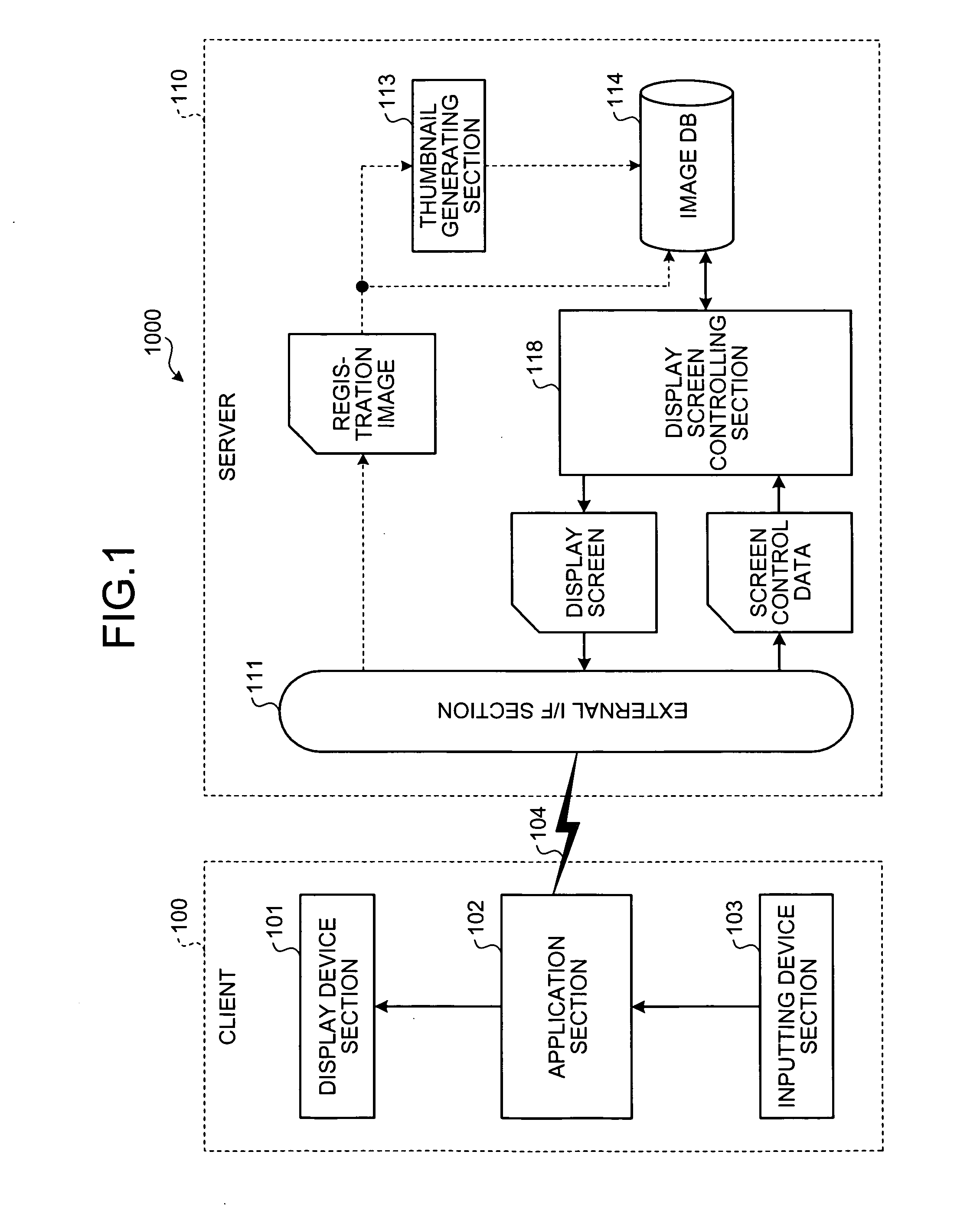
[0052]FIG. 1 is a block diagram of a configuration of an image processing system 1000 according to the present invention. In the image processing system 1000, a client 100 and a server 110 are connected by an external communication path 104. The client 100 is an information processing device, such as a personal computer, a personal digital assistant (PDA), or a mobile phone. The server 110 is an information processing device such as a personal computer. The external communication path 104 is a network, such as a local area network (LAN), an intranet, Ethernet (registered trademark), or the Internet.

[0053]A functional configuration of the client 100 will be described. The client 100 includes a display device section 101, an application section 102, and an inputting device section 103. The display device section 101 displays an image. The inputting device section 103 receives input of instructions from a user. The application section 102 includes an application program, or a plurality...

third embodiment

[0102]Next, a process by which the server 110 generates the thumbnail images will be described. the server 110 performs the procedures at Step S10 to Step S11 in FIG. 5. The server 110 then hierarchically codes the maximum size thumbnail images and stores the pieces of encoded data (the hierarchically coded thumbnail) in the image DB 114, without performing the procedures at Step S12 to Step S13.

[0103]Next, a process by which the server 110 generates the thumbnail list view of the thumbnail list display screen will be described. FIG. 24 is a flowchart of the process for generating the thumbnail list view of the thumbnail list display screen performed by the server 110. As according to the first embodiment, the server 110 sets the display magnification and the display area 307 of the thumbnail list view in adherence to the screen control data at Step S201. The server 110 then sets a resolution level to be used for the display based on the set display magnification (Step S302). Next,...

fourth embodiment

[0132] the thumbnail generating section 413 is configured to have two sets of a set including a magnification change processing section and a hierarchical code processing section. However, the thumbnail generating section 413 can have only one set of the magnification change processing section and the hierarchical code processing section and generate two hierarchically coded thumbnails, the first hierarchically coded thumbnail and the second hierarchically coded thumbnail, in a time series. The two hierarchically coded thumbnails, the first hierarchically coded thumbnail and the second hierarchically coded thumbnail, are given as examples. However, more hierarchically coded thumbnails can be generated, increasing variation in the image sizes of the thumbnail image that can be displayed.

[0133]In FIG. 33, an example is shown in which the two hierarchically coded thumbnails, the first hierarchically coded thumbnail and the second hierarchically coded thumbnail, are used for extremely s...


PUM


Abstract

A thumbnail generating section of a server generates a plurality of thumbnail images from a registration image received through an external I / F section and stores the generated thumbnail images in an image DB. The image DB stores therein registration images received through the external I / F section and the thumbnail images generated by the thumbnail generating section. A display screen controlling section generates a display screen to be displayed by a client. The display screen controlling section controls the display screen by generating the display screen in adherence to screen control data transmitted from the client.

Description

CROSS-REFERENCE TO RELATED APPLICATIONS[0001]The present application claims priority to and incorporates by reference the entire contents of Japanese priority document 2007-169634 filed in Japan on Jun. 27, 2007.BACKGROUND OF THE INVENTION[0002]1. Field of the Invention[0003]The present invention relates to technology for displaying thumbnail images on a display screen.[0004]2. Description of the Related Art[0005]Electronic filing devices are known in the art that digitalize paper documents using a scanner. Such devices have been used for commercial purposes in which a large number of paper documents are handled. In recent years, ease-of-handling and convenience of such devices are also receiving recognition in common offices because of availability of low-cost scanners, popularity of multifunction printers (MFP), and legislation regarding electronic documents (e-documents) and the like. As a result, instances in which paper documents are scanned and digitalized are increasing. Uses...

Claims


Application Information

Patent Timeline
IPC IPC(8): G06F3/048G06F3/0484
CPCH04N1/00244H04N1/00453H04N1/32101H04N2201/325H04N2201/3273H04N2201/3274H04N2201/3278G09G5/14G09G2340/04G06F16/51
Inventor KOBAYASHIINAMOTO, HIROHISAKIHARA, YUKA
Owner RICOH KK
Learn More