Method for manufacturing a preform for optical fibres by means of a vapour deposition process

a vapour deposition and manufacturing method technology, applied in the direction of chemical vapor deposition coating, glass making apparatus, coating, etc., can solve the problems of high internal stress of quartz, low quality quartz present in the interior of the substrate tube may adversely affect the substrate tube, and formation of gas bubbles elsewhere in the substrate tube, so as to reduce the risk of clogging of the insert tub

Active Publication Date: 2009-01-01
DRAKA COMTEQ BV
View PDF15 Cites 23 Cited by
  • Summary
  • Abstract
  • Description
  • Claims
  • Application Information

AI Technical Summary

Benefits of technology

[0010]One object of the present invention is thus to provide a method for manufacturing a preform for optical fibres

Problems solved by technology

Examples of such a low-quality quartz layers are so-called soot rings, but also but also quartz having a high internal stress caused by a high dopant content.
The present inventors have found that such low quality quartz present in the interior of the substrate tube may adversely affect the substrate tube, in particular as a result of the formation of gas bubbles in the vicinity of the supply side of the substrate tube upon collapsing the hollow substrate tube into a solid preform.
In addition to that, the present inventors have found that such low quality quartz may come loose from the interior of the hollow substrate tube during the collapsing process, which may lead to contamination or to the formation of gas bubbles elsewhere in the substrate tube.
Another negative aspect is the fact that cracks may occur in the low quality quartz region, which cracks may propagate in the direction of the center of the substrate tube, which is undesirable.
The present inventors have furthermore found that the low quality quartz may lead to clogging of the substrate tube and the associated piping, as a result of which the pressure

Method used


Image

  • Method for manufacturing a preform for optical fibres by means of a vapour deposition process
  • Method for manufacturing a preform for optical fibres by means of a vapour deposition process

Examples


example

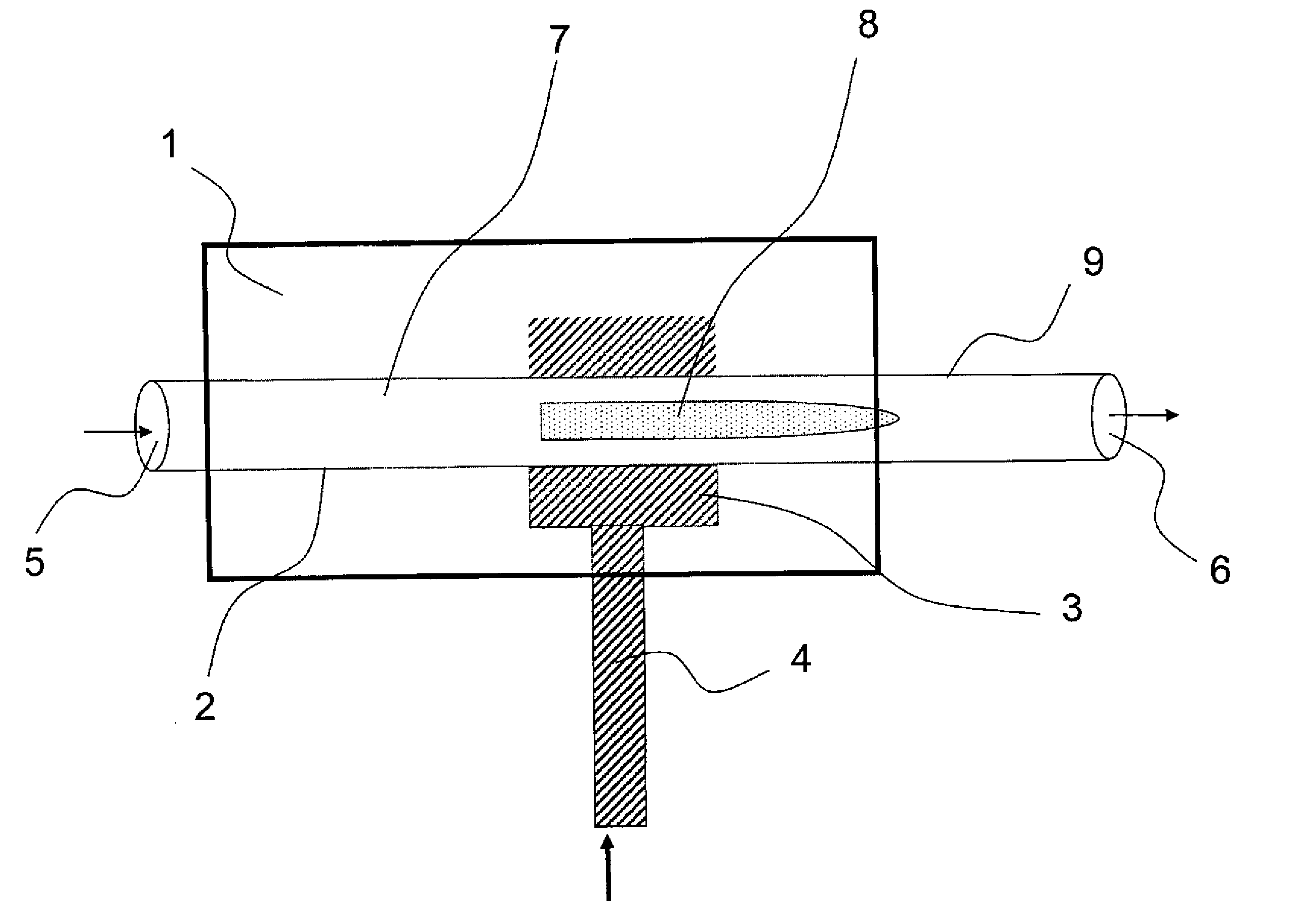
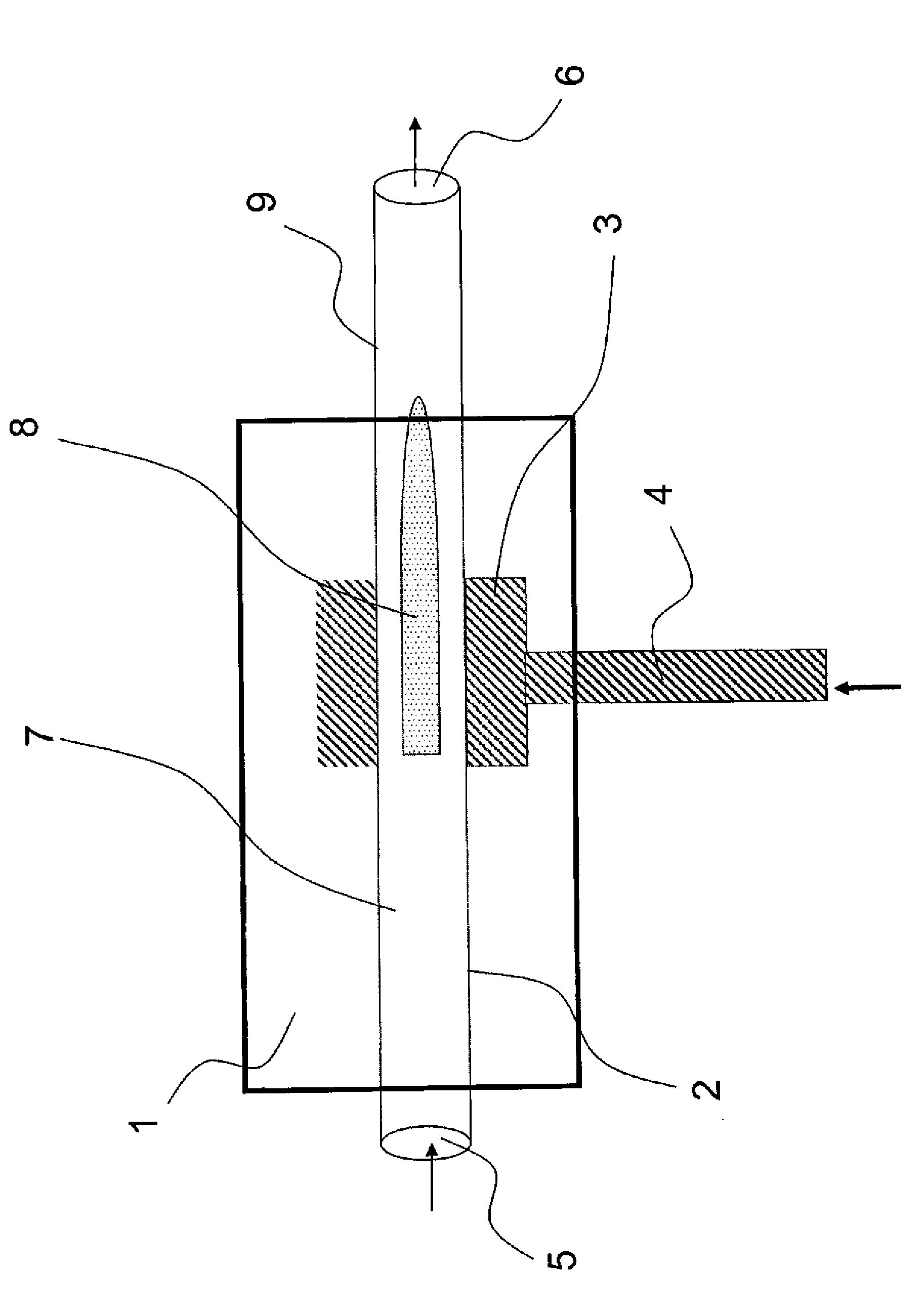
[0036]Referring to FIG. 1, a hollow substrate tube 2 made of quartz was manufactured by means of a standard PCVD process as known from Dutch patent NL 1 023 438 in the name of the present applicant. The hollow substrate tube 2 having a supply side 5 and a discharge side 6 was placed in a furnace 1, in which furnace 1 a resonator 3 is present, which resonator 3 can move back and forth along the length of the hollow substrate tube 2 within the furnace 1. Microwave energy was supplied to the resonator 3 via the waveguide 4 so as to create plasma conditions in the interior 7 of the hollow substrate tube 2, which plasma conditions function to deposit glass layers on the interior 7 of the hollow substrate tube 2. Disposed within the hollow substrate tube 2, near the discharge side 6 of the hollow substrate tube 2, is a so-called insert tube (not shown), in which insert tube deposition of soot takes place near the location indicated at 9. Such an insert tube has an external diameter which ...


PUM

PropertyMeasurementUnit
Plasma poweraaaaaaaaaa

Abstract

The present invention relates to a method for manufacturing a preform for optical fibres by means of a vapour deposition process, wherein an intermediate step is carried out between one deposition phase and the next deposition phase(s), wherein the intermediate step comprises supplying an etching gas to the supply side of the hollow substrate tube.

Description

CROSS-REFERENCE TO RELATED APPLICATION[0001]This application claims priority to Netherlands Patent Application No. 1034059 filed Jun. 29, 2007, the contents of which are incorporated by reference herein.TECHNICAL FIELD AND BACKGROUND OF THE INVENTION[0002]The present invention relates to a method for manufacturing a preform for optical fibres by means of a vapour deposition process.[0003]A device for manufacturing a preform for optical fibres by means of a vapour deposition process is known per se from Korean patent application No. 2003-774,952. Using the device that is known therefrom, an optical preform is made by means of an MCVD (Modified Chemical Vapour Deposition) process, in which a discharge tube and an insert tube are used, which discharge tube is attached to the substrate tube. The insert tube is disposed within the discharge tube and has an external diameter which is smaller than that of the discharge tube. Disposed within the insert tube is a soot scraping element, which...

Claims


Application Information

Patent Timeline
IPC IPC(8): C23C16/00
CPCC03B37/01815C03B2201/31C03B2201/12C03B37/0183
Inventor HARTSUIKER, JOHANNES ANTOONMILICEVIC, IGORVAN STRALEN, MATTHEUS JACOBUS NICOLAASDECKERS, ROB HUBERTUS MATHEUSKORSTEN, MARCO
Owner DRAKA COMTEQ BV
Why Eureka
Try Eureka