Integrated Wet Wipe and Disposal Bag Dispenser Unit

Pending Publication Date: 2022-09-08
SIMMONS TAMMY
View PDF25 Cites 1 Cited by
  • Summary
  • Abstract
  • Description
  • Claims
  • Application Information

AI Technical Summary

Benefits of technology

The present invention is a wet wipe dispensing and disposing device consisting of a housing with a hinged door and a top lid. The device stores a set of interfolded wet wipes in a slot and flap in the hinged door for individual dispensing and a set of stacked plastic waste bags in a separate top opening for individual dispensing and disposal of the used wet wipes. The method involves pulling out a wet wipe and a waste bag, placing the used wet wipe in the waste bag, and sealing it in a trash receptacle to prevent clogging of sewer lines. This invention solves the problem of clogging sewer lines and related conduits due to used wet wipes.

Problems solved by technology

This is due to their habit of flushing the wipes and also due to the absence of any disposal bag readily available in the bathroom.
Many of the wet wipes currently available are marketed as flushable, however, they do not disintegrate easily after flushing, and can end up clogging home sewer / septic systems and sewage treatment plants.
The aforementioned can lead to serious blockages in the pipes, drains and pumps that can cause sewage back-up in homes and businesses.
These formations can create huge clogs in plumbing pipes and drains that are commonly found in houses and other dwellings.
Repairing and clearing of such clogs can cost thousands of dollars.
Similarly, when wet wipes reach a sewer system they can clog the sewer lines, drains, pumps and septic tanks.
Further, there is a long felt need in the art for an improved wet wipe dispensing system that saves extensive amounts of money on maintenance and repair of clogged pipes.

Method used


Image

  • Integrated Wet Wipe and Disposal Bag Dispenser Unit
  • Integrated Wet Wipe and Disposal Bag Dispenser Unit
  • Integrated Wet Wipe and Disposal Bag Dispenser Unit

Examples


Embodiment Construction

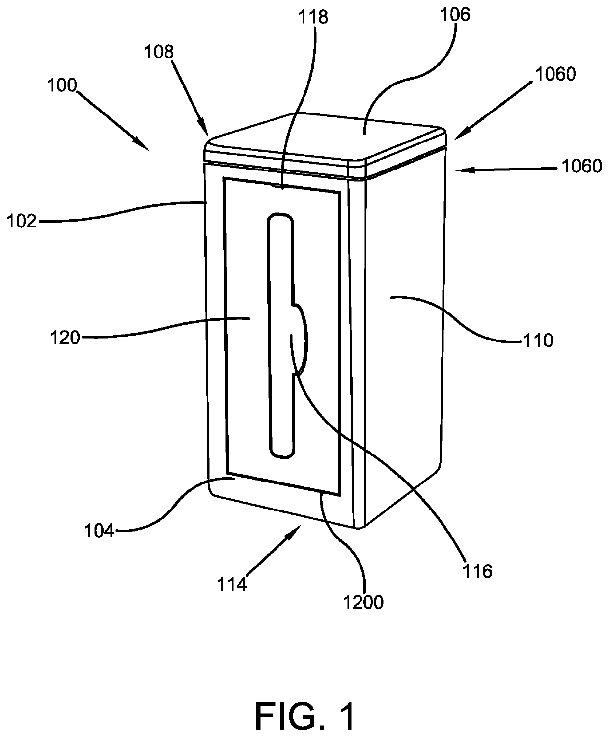
[0028]The innovation is now described with reference to the drawings, wherein like reference numerals are used to refer to like elements throughout. In the following description, for purposes of explanation, numerous specific details are set forth in order to provide a thorough understanding thereof. It may be evident, however, that the innovation can be practiced without these specific details. In other instances, well-known structures and devices are shown in block diagram form in order to facilitate a description thereof. Various embodiments are discussed hereinafter. It should be noted that the figures are described only to facilitate the description of the embodiments. They are not intended as an exhaustive description of the invention and do not limit the scope of the invention. Additionally, an illustrated embodiment need not have all the aspects or advantages shown. Thus, in other embodiments, any of the features described herein from different embodiments may be combined.

[0...


PUM


Abstract

The present invention relates to a combination bathroom wet wipe dispenser and disposal unit, capable of being mounted to the wall near a toilet. The unit stores a replaceable wet wipe dispenser unit and an individual waste bag dispenser unit within a housing. The wet wipe dispenser unit is placed proximal to a front wall of the housing, and an individual wet wipe is dispensed from a slot disposed through a hinged door of the front wall that is aligned with a wipe dispensing slit of the wet wipe dispenser unit. The hinged door can be opened to replace the wet wipe dispenser unit and / or waste bag dispenser unit. The waste bag dispenser unit can be placed proximal to the rear wall of the housing for storing a stack of waste bags, wherein an individual waste bag can be dispensed from the top lid of the housing.

Description

CROSS-REFERENCE TO RELATED APPLICATION[0001]The present application claims priority to, and the benefit of, U.S. Provisional Application No. 63 / 156,650, which was filed on Mar. 4, 2021 and is incorporated herein by reference in its entirety.FIELD OF THE INVENTION[0002]The present invention relates generally to the field of wipe dispensing systems. More specifically, the present invention relates to an improved wet wipe dispensing and disposal system for toilets. The system provides users with a bathroom wet wipe dispenser and disposal tool used to dispense individual wet wipes for use and application, and individual waste bags for disposing of the used wet wipes. The system features a replaceable container for dispensing individual wet wipes from the front of the system. and an individual waste bag dispenser allowing users to pull out a bag for sealing away used wet wipes for disposal. The system can be placed on a floor or can be mounted to a wall. Accordingly, the present disclosu...

Claims


Application Information

Patent Timeline
IPC IPC(8): A47K10/46B65D83/08B65F1/00B65D43/16B65D25/22A47K10/42
CPCA47K10/46B65D83/0805B65F1/0026B65D43/16B65D25/22A47K10/426A47K2010/3266B65F1/1426A47K2201/02
Inventor SIMMONS, TAMMY
Owner SIMMONS TAMMY
Why Eureka
Try Eureka