
Liquid crystal display and driving method thereof

a technology of liquid crystal display and driving method, which is applied in the direction of static indicating device, non-linear optics, instruments, etc., can solve the problems of slow response speed due to characteristics of liquid crystal, viscosity, elasticity, etc., and achieve the effect of minimizing heat generation of circuit and emi and improving the response characteristics of liquid crystal

Active Publication Date: 2009-01-01
LG DISPLAY CO LTD
View PDF2 Cites 14 Cited by
  • Summary
  • Abstract
  • Description
  • Claims
  • Application Information

AI Technical Summary

Benefits of technology

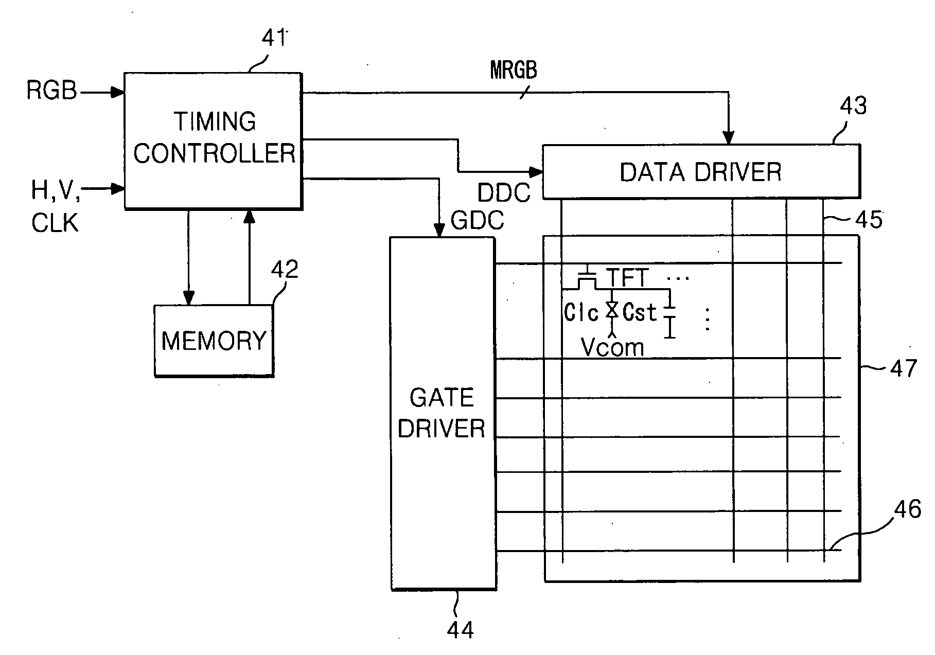
[0015]An object of the present invention is to provide a liquid crystal display device and a driving method thereof that is adapted to minimizing heat generation of a circuit and EMI by reducing data transitions between a lookup table and a memory in a circuit that modulates digital video data to improve response characteristics of liquid crystal.

Problems solved by technology

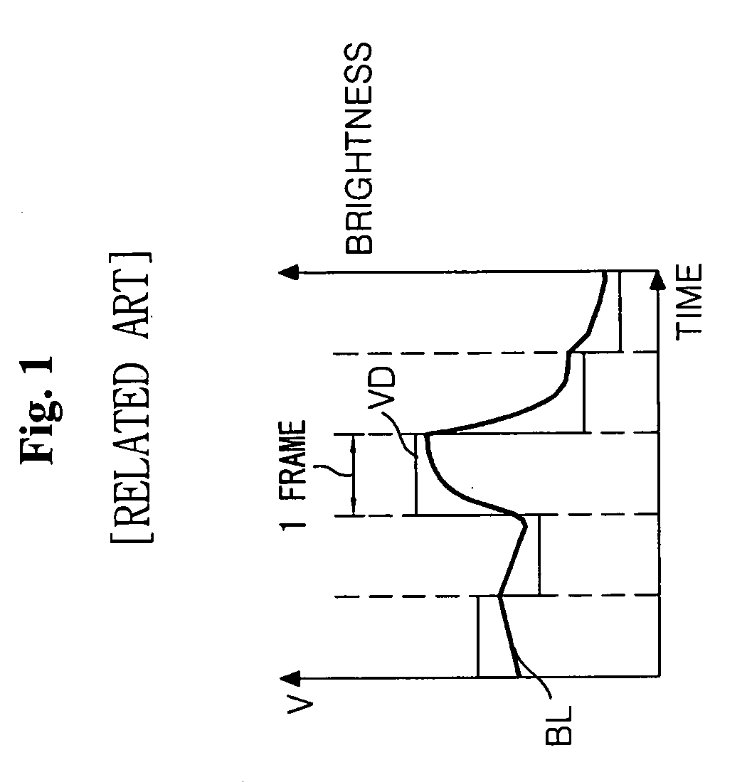
Equations 1 and 2 show the disadvantages of liquid crystal display devices, such as slow response speeds due to characteristics of liquid crystals, such as viscosity, elasticity, and other properties.
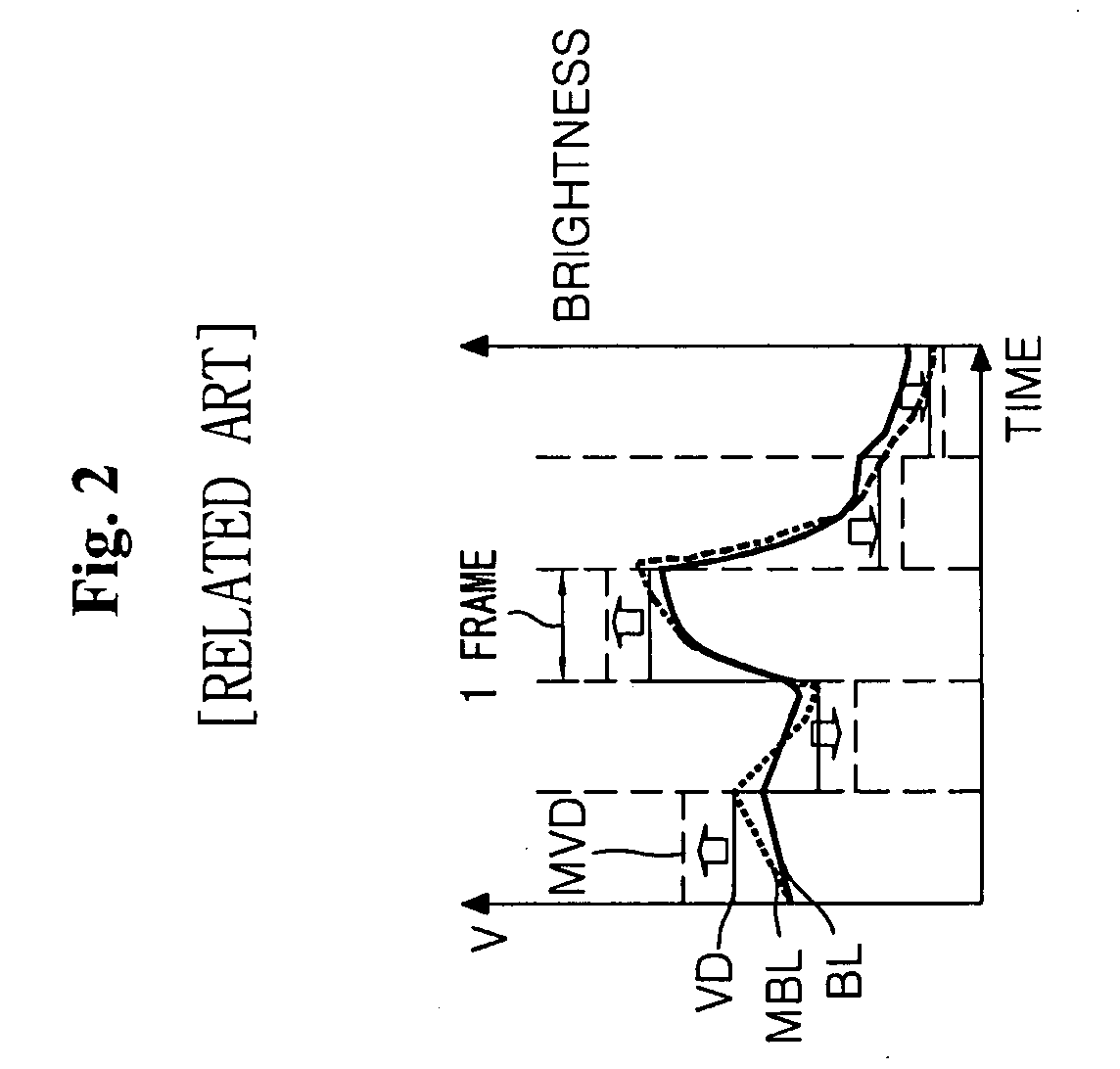
As shown in FIG. 1, a liquid crystal display device of the related art cannot properly render a desired color and brightness because display brightness BL corresponding thereto does not reach the desired brightness due to the slow response speed of the liquid crystal when data VD is changed from one level to another level.
As a result, in the liquid crystal display device, a motion blurring phenomenon in a motion picture is generated and the picture quality thereof decreases due to the reduction of contrast ratio.
The frame memory 33 included in a liquid crystal display device is a major cause of increased circuit cost.
In such a case, other problems exist, such as increased electromagnetic interference (EMI) in a data transmission path between the timing controller and the frame memory 33 and increased heat generation of the timing controller.
In addition, size of the chip of the timing controller becomes large.

Method used


Image

  • Liquid crystal display and driving method thereof
  • Liquid crystal display and driving method thereof
  • Liquid crystal display and driving method thereof

Examples


Embodiment Construction

[0034]Reference will now be made in detail to the embodiments of the present invention, examples of which are illustrated in the accompanying drawings.

[0035]As shown in FIG. 4, a liquid crystal display device according to an exemplary embodiment of the present invention includes a liquid crystal display panel 47 having data lines 45 crossing gate lines 46 and thin film transistors (“TFTs”) for driving liquid crystal cells Clc formed at the crossing parts thereof. A data driver 43 supplies data to the data lines 45 of the liquid crystal display panel 47, and a gate driver 44 supplies scan pulses to the gate lines 46 of the liquid crystal display panel 47. A timing controller 41 controls the data driver 43 and the gate driver 44 and supplies source data RGB to a memory 42 connected to the timing controller 41.

[0036]In the liquid crystal display panel 47, liquid crystal is injected between two glass substrates. On one glass substrate, data lines 45 and gate lines 46 are formed to perpe...


PUM


Abstract

A liquid crystal display device includes a data transition part to compare a number of transitions between a previous data and a current data to selectively invert the current data and to generate a reverse signal, a memory to store the data from the data transition part and to output the stored data as the previous frame data, a data reverse transition part to reversely convert the data from the memory using the reverse signal, a lookup table to compare the current data and the previous frame data reversely converted by the data reverse transition part to select a modulated data, and a display drive circuit to display the data from the lookup table on a liquid crystal display panel.

Description

[0001]This application claims the benefit of the Korean Patent Application No. P07-063058 filed on Jun. 26, 2007, which is hereby incorporated by reference.BACKGROUND OF THE INVENTION[0002]1. Field of the Invention[0003]The present invention relates to a liquid crystal display and driving method thereof, and more particularly to a liquid crystal display and driving method thereof that is adapted to minimizing heat generation of a circuit and electromagnetic interface (EMI).[0004]2. Discussion of the Related Art[0005]A liquid crystal display device controls the light transmittance of liquid crystal cells in accordance with video signals, thereby displaying a picture. Among liquid crystal display devices, an active matrix type liquid crystal display device, which includes a switch device formed at each liquid crystal cell, is advantageous in displaying a motion picture because the switch device may be actively controlled. A thin film transistor (hereinafter, referred to as “TFT”) is m...

Claims


Application Information

Patent Timeline
Patent Type & Authority Applications(United States)
IPC IPC(8): G09G3/36
CPCG09G3/3611G09G2320/0252G09G2320/0261G09G2340/16G09G2330/06G09G2340/02G09G2330/021G02F1/133G09G3/20G09G3/36
Inventor KOO, SUNG JOJANG, SU HYUKLEE, SONG JAESONG, HONG SUNGMIN, WOONG KI
Owner LG DISPLAY CO LTD
Learn More