Thermal barrier deposited directly on monocrystalline superalloys

Inactive Publication Date: 2008-12-25
SN DETUDE & DE CONSTR DE MOTEURS DAVIATION S N E C M A
View PDF2 Cites 0 Cited by
  • Summary
  • Abstract
  • Description
  • Claims
  • Application Information

AI Technical Summary

Benefits of technology

[0007]The invention seeks to provide a method that makes it possible to increase the lifetime of a superalloy coated in a thermal barrier, while simplifying the fabrication flow-process for said assembly and reducing its fabrication cost.
[0010]By means of the above provisions, the fabrication flow process for the thermal barrier is simplified. Firstly there is no need to deposit the underlayer since the zirconia is deposited directly on the superalloy without any underlayer. Secondly it is possible to drill holes immediately after the MCNG superalloy part has been machined, where those two operations (drilling and machining) are preferably performed in the same workshop. The risks of the surface of the superalloy being contaminated are thus minimized. After the drilling operation, the part is taken directly to the workshop for depositing the final ceramic layer.
[0011]Compared with prior art alloys, the lifetime of a superalloy having a thermal barrier deposited thereon by the method of the present invention is lengthened. This is due in particular to the fact that the zirconia-based ceramic deposited on an MCNG superalloy is less sensitive to the above-described phenomenon of the alumina layer undulating. Tests have shown that oxidation at the interface between the zirconia and the MCNG superalloy takes place in more uniform and rectilinear manner than oxidation of a conventional underlayer. The physical bonding between the alumina and the ceramic thus occupies a larger area than with AM1.

Problems solved by technology

In that environment, the superalloys that presently provide the best high temperature performance (ideally monocrystalline superalloys) present mechanical performance and lifetime that are not sufficient.
Nevertheless, the use of such an underlayer presents several drawbacks.
Depositing the underlayer leads to additional material and process cost.
In addition, it makes the overall method of fabricating the part coated in the thermal barrier more complex.
In such situations, the underlayer must be deposited before drilling the holes that are included in the superalloy part, otherwise the electrolytic deposition of the underlayer runs the risk of obstructing holes of small diameter.
These trips are undesirable since they increase the risk of the surface of the part being contaminated by foreign elements that can reduce the bonding capacity of the ceramic that is subsequently deposited on said surface.
Furthermore, the layer of alumina (oxidation layer) tends to undulate so as to follow deformations in the underlayer, thereby leading to regions where the ceramic is held by the alumina in spots only and from which the ceramic becomes detached prematurely.
Once the ceramic has begun to spall, the part deteriorates rapidly and is no longer capable of providing the required performance.

Method used


Image

  • Thermal barrier deposited directly on monocrystalline superalloys

Examples


Embodiment Construction

[0019]Preferably, the zirconia can be stabilized with at least one oxide of an element selected from the group constituted by dysprosium, erbium, europium, gadolinium, samarium, ytterbium, yttrium, or with a combination of a tantalum oxide and at least one oxide of an element in this group, or with a combination of a niobium oxide and at least one oxide of an element in this group.

[0020]More preferably, the zirconia is stabilized with an yttrium oxide.

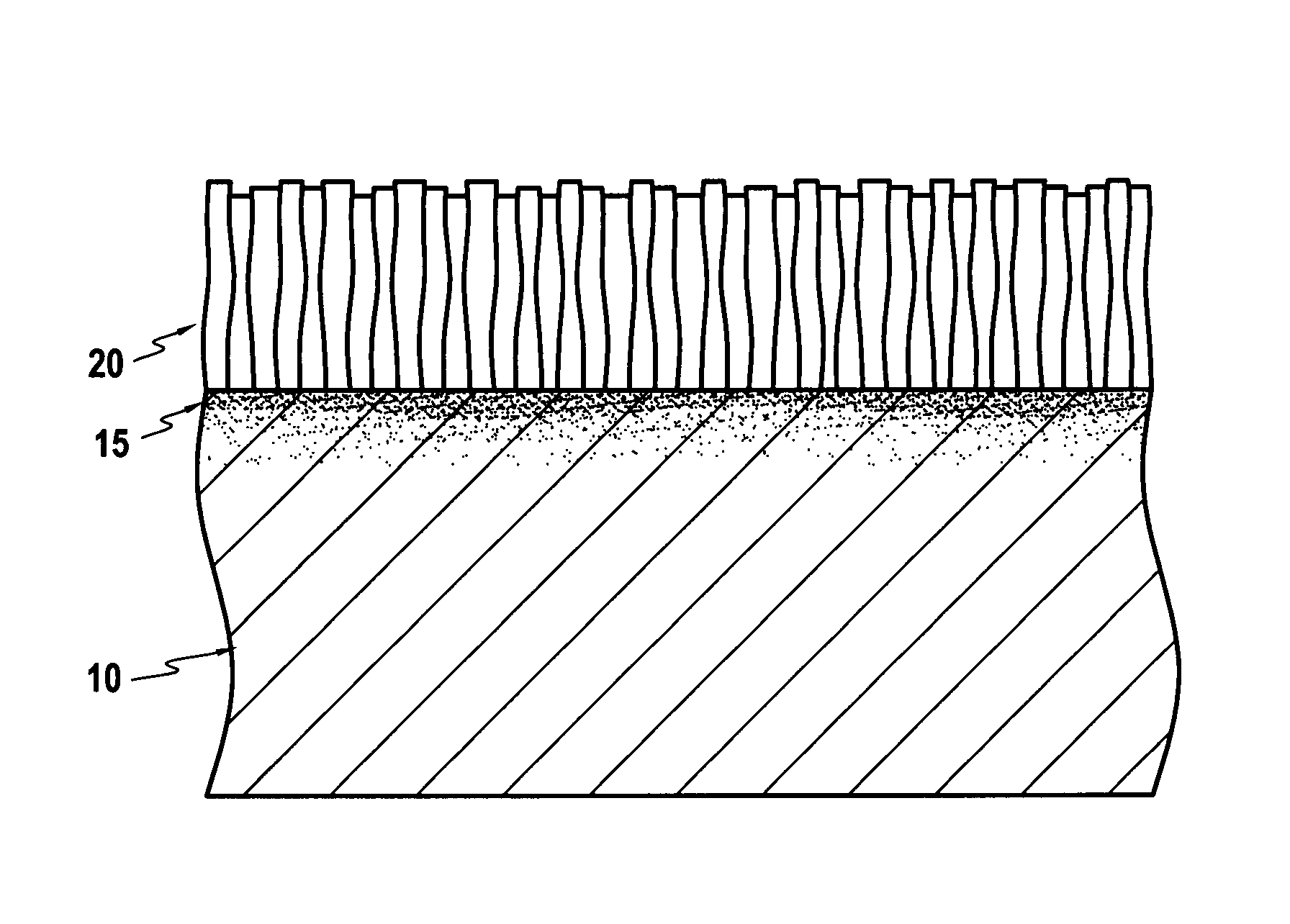
[0021]The ceramic is deposited by the electron beam physical vapor deposition (EBPVD) method. The ceramic is supplied in the form of a powder that, once vaporized by the electron beam, condenses on the MCNG superalloy to form a ceramic layer 20. Because an electron beam is used, it is necessary to maintain a primary vacuum in the enclosure containing the electron beam, the ceramic for deposition, and the MCNG superalloy substrate. The ceramic layer 20 deposited by the EBPVD method presents a structure in the form of adjacent columns 22...


PUM

PropertyMeasurementUnit
Fractionaaaaaaaaaa
Fractionaaaaaaaaaa
Fractionaaaaaaaaaa

Abstract

The invention relates to the field of superalloys coated in a thermal barrier. On a monocrystalline superalloy having the following composition by weight: 3.5% to 7.5% Cr, 0 to 1.5% Mo, 1.5% to 5.5% Re, 2.5% to 5.5% Ru, 3.5% to 8.5% W, 5% to 6.5% Al, 0 to 2.5% Ti, 4.5% to 9% Ta, 0.08% to 0.12% Hf, 0.08% to 0.12% Si, the balance to 100% being constituted by Ni and any impurities, a stabilized zirconia is deposited directly, the zirconia being stabilized with at least one oxide of an element selected from the group constituted by rare earths, or with a combination of a tantalum oxide and at least one rare earth oxide, or with a combination of a niobium oxide and at least one rare earth oxide.

Description

[0001]The present invention relates to a method of depositing a thermal barrier on a monocrystalline superalloy.BACKGROUND OF THE INVENTION[0002]High pressure turbine blades in turbomachines need to conserve their mechanical properties, their resistance to corrosion, and their resistance to oxidation in the aggressive environment of gas at very high temperature (more than 1000° C.) ejected at high speed. In that environment, the superalloys that presently provide the best high temperature performance (ideally monocrystalline superalloys) present mechanical performance and lifetime that are not sufficient. That is why it is necessary to cover such superalloys with a thermal barrier. By way of example, a superalloy commonly in use is the alloy known as AM1, which is a nickel-based superalloy in accordance with U.S. Pat. No. 4,639,280, having the following composition by weight: 5% to 8% Co, 6.5% to 10% Cr, 0.5% to 2.5% Mo, 5% to 9% W, 6% to 9% Ta, 4.5% to 5.8% Al, 1% to 2% Ti, 0 to 1....

Claims


Application Information

Patent Timeline
IPC IPC(8): C22C19/05
CPCC22C19/057C22C19/058Y02T50/6765Y02T50/67C23C28/042C23C30/00Y02T50/60
Inventor BOURLIER, FLORENT DIDIER ANDRELE BIAVANT, KRISTELL
Owner SN DETUDE & DE CONSTR DE MOTEURS DAVIATION S N E C M A
Why Eureka
Try Eureka