
Curtain airbag system

a technology of airbags and airbags, which is applied in the direction of pedestrian/occupant safety arrangements, vehicular safety arrangements, vehicle components, etc., can solve the problems of airbag burst or rupture, airbag damage of airbags, and so as to reduce the damage of airbags and improve the delay in airbag deployment

Active Publication Date: 2008-12-18
AUTOLIV DEV AB
View PDF6 Cites 11 Cited by
  • Summary
  • Abstract
  • Description
  • Claims
  • Application Information

AI Technical Summary

Benefits of technology

[0007]The present invention has been made to address the above problems, and accordingly an object thereof is to provide a curtain airbag system with an airbag that is resistant to bursting by improving the flat pattern shape of airbag without putting an inner tube (or a reinforcing cloth) in a duct.
[0011]In at least one embodiment of the curtain airbag system of the present invention, by improving the flat pattern shape of airbag as described above, the internal pressure of the duct at the early stage of deployment is restricted to a pressure not higher than the burst limit value so that gas for deployment smoothly reaches a portion in the duct that is substantially spaced apart from a gas ejection hole of an inflator. Thereby, bag damage of airbag can be reduced, and the delay in deployment of airbag can be improved.

Problems solved by technology

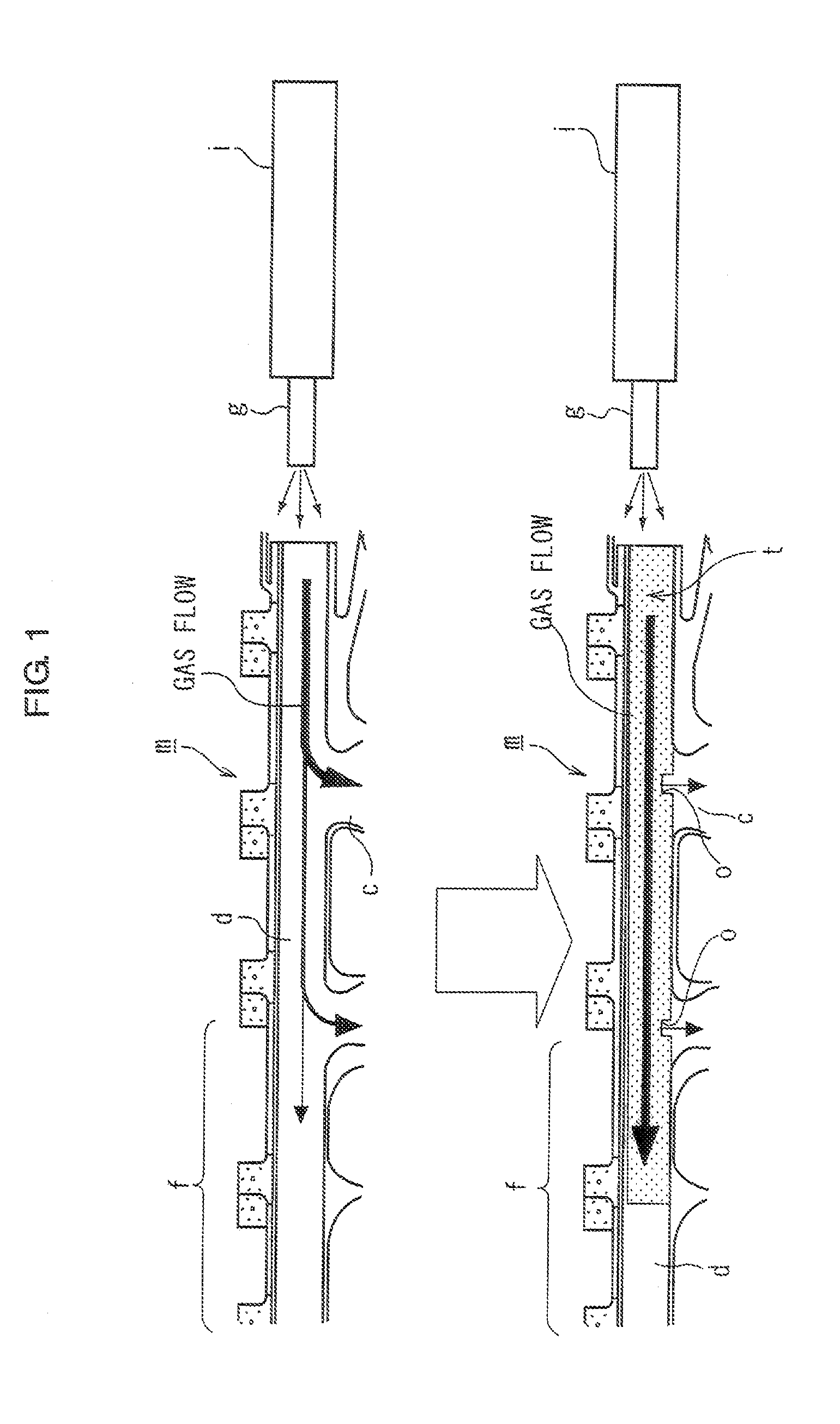
Then, a gas attack (e.g. overpressure condition which may lead to “bursting”) occurs in the duct (d), which makes it difficult for the gas for deployment to reach a front part (f) of the duct (d).
Accordingly, the deployment of the front part of the airbag may be delayed, or the airbag may burst or rupture.
However, if the inner tube (t) is put in the duct (d), the package size at the storage time of the curtain airbag system (m) increases, which may make the airbag system (m) incapable of being stored on the roof side rail of the vehicle.
Also, if the inner tube (t) is put in the duct (d), the cost of the curtain airbag system (m) becomes high.

Method used


Image

  • Curtain airbag system
  • Curtain airbag system
  • Curtain airbag system

Examples


Embodiment Construction

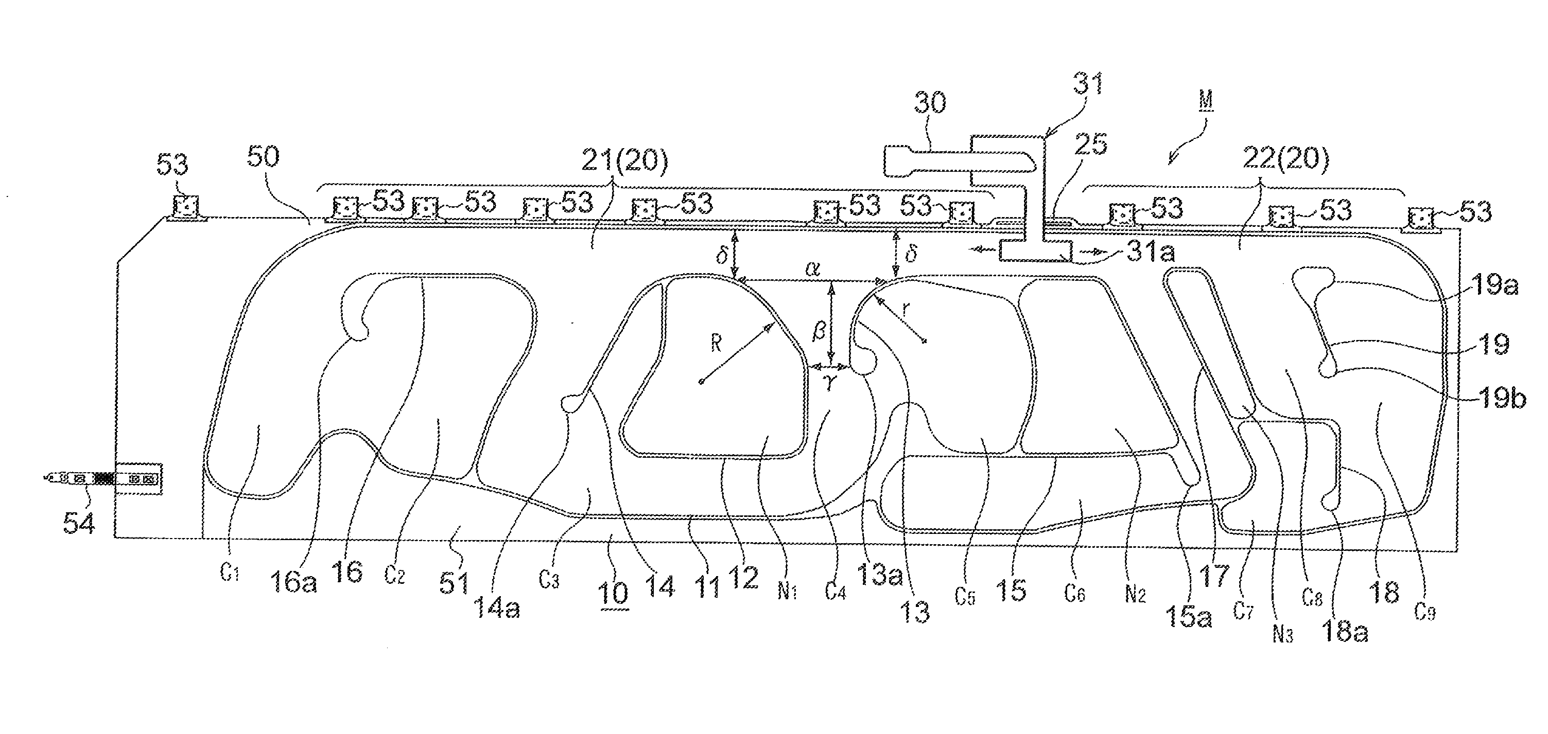
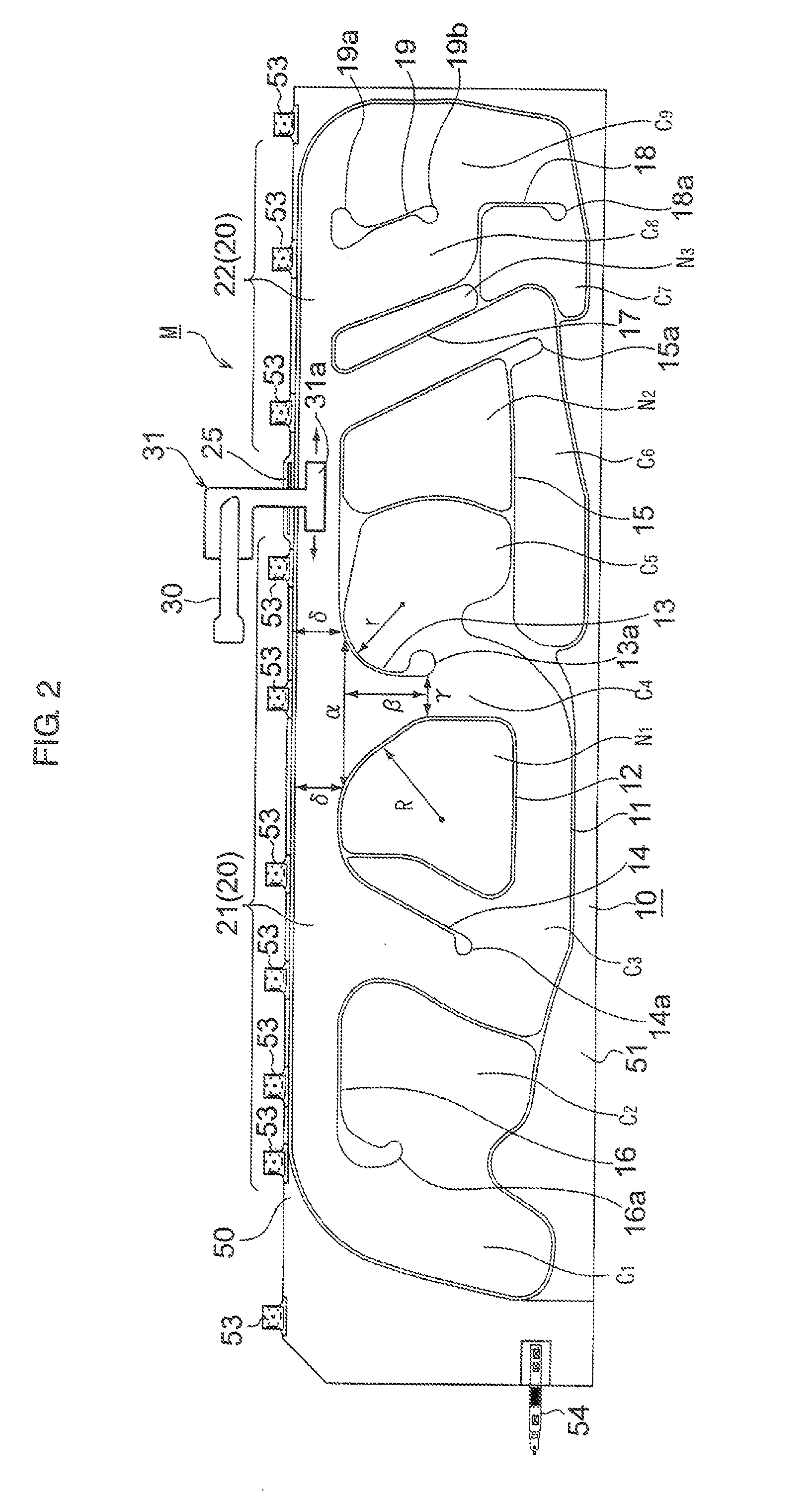
[0015]One example of an embodiment of the present invention will now be described in detail with reference to the accompanying drawings. FIG. 2 is a front view of a curtain air bag system in accordance with the embodiment of the present invention, and FIG. 3 is a front view of a portion of the curtain airbag system shown in FIG. 2 for explaining the flow of gas for deployment therein.

[0016]An airbag 10 of a curtain airbag system M is stored on a roof side rail of a vehicle in a folded state. The folded airbag 10 is disposed over almost the entire length in the vehicle front and rear directions along the roof side rail. In case of emergency, gas for deployment, which is sent from an inflator 30, is introduced through a gas introduction hole 25 of the airbag 10, and thereby the airbag 10 is expandingly deployed in a curtain form along the side surface of the vehicle. The airbag 10 is for receiving the heads of passengers seated on the front seat and the rear seat in the vehicle to pro...


PUM


Abstract

An airbag is disposed over almost the entire length along a roof side rail. The airbag comprises a duct formed with a gas introduction hole and a plurality of chambers communicating with the duct. The duct comprises a long first duct part and a short second duct part arranged with the gas introduction hole being provided therebetween. The inlet of a chamber closest to the gas introduction hole in the first duct part has a shape that becomes narrower gradually from the upper part toward the lower part. The passage width of the uppermost part of the inlet of the closest chamber is greater than the depth to the narrowest part thereof, and the passage width of the narrowest part is narrower than the passage width of the first duct part around the inlet thereof.

Description

CROSS REFERENCES TO RELATED APPLICATIONS[0001]This application claims priority to Japanese Patent Application No. 2007-156093 filed on Jun. 13, 2007.FIELD OF THE INVENTION[0002]The present invention relates to a curtain airbag system that is configured so that an airbag is stored on a roof side rail of a vehicle and is deployed along a side door window and the like in case of emergency.BACKGROUND OF THE INVENTION[0003]A curtain airbag system is configured so that in an emergency event such as in a side collision, rollover, or the like, gas for deployment is introduced from an inflator into an airbag that is stored on a roof side rail. The airbag is deployed along a side door window and the like to protect the passengers' heads. A curtain airbag system of this type is disclosed, for example, in Japanese Patent Laid-Open No. 2004-268608.[0004]In the case where a high-output inflator (i) is used for a curtain airbag system (m) of this type, as shown in FIG. 1, gas for deployment collec...

Claims


Application Information

Patent Timeline
Patent Type & Authority Applications(United States)
IPC IPC(8): B60R21/213B60R21/20B60R21/232
CPCB60R21/232B60R21/26B60R2021/2612
Inventor OHBA, YOSHIHIRO
Owner AUTOLIV DEV AB
Learn More