
Insulated gate bipolar transistor

a bipolar transistor and gate technology, applied in transistors, electrical devices, semiconductor devices, etc., can solve problems such as difficult discharge control and variation in switching characteristics

Inactive Publication Date: 2008-12-18
SANYO ELECTRIC CO LTD +1
View PDF14 Cites 13 Cited by
  • Summary
  • Abstract
  • Description
  • Claims
  • Application Information

AI Technical Summary

Benefits of technology

[0059]In the insulated gate bipolar transistor of the invention, even if it has the NPT structure, the IGBT of the embodiment minimizes reduction of electron current density, prevents a variation in characteristics, and attains a sufficient conductivity modulation effect.

Problems solved by technology

Furthermore, during the off state of the IGBT 81, it is difficult to control the discharge of the holes entering this portion, thereby causing a variation in switching characteristics.

Method used


Image

  • Insulated gate bipolar transistor
  • Insulated gate bipolar transistor
  • Insulated gate bipolar transistor

Examples


Embodiment Construction

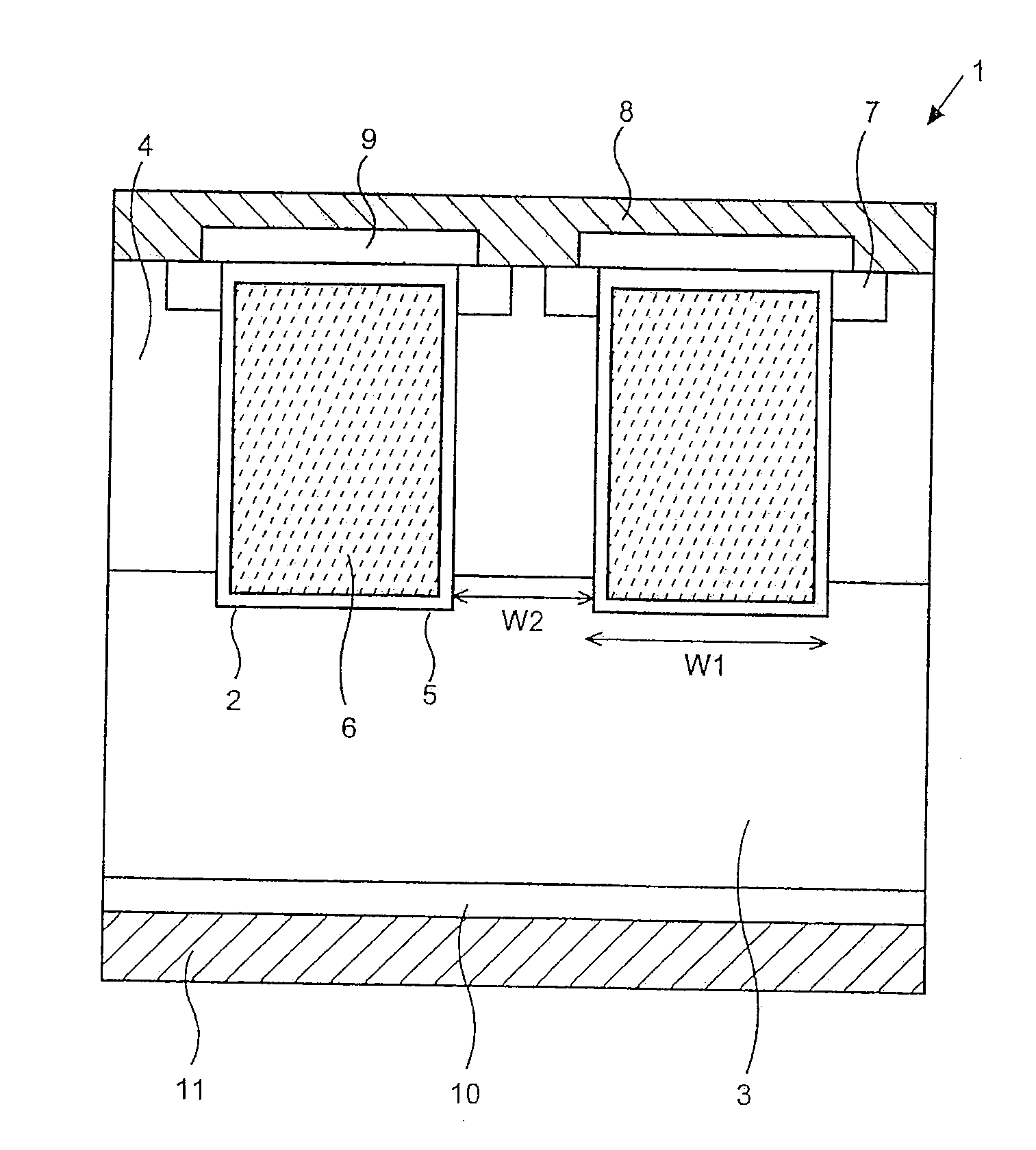
[0026]An embodiment of an insulated gate bipolar transistor of the invention will be described referring to figures in detail.

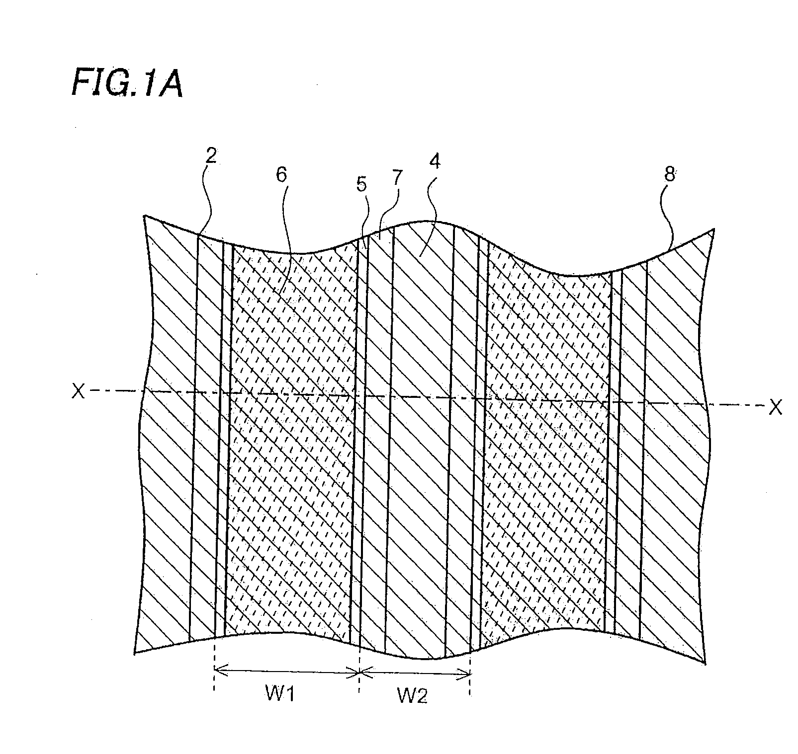
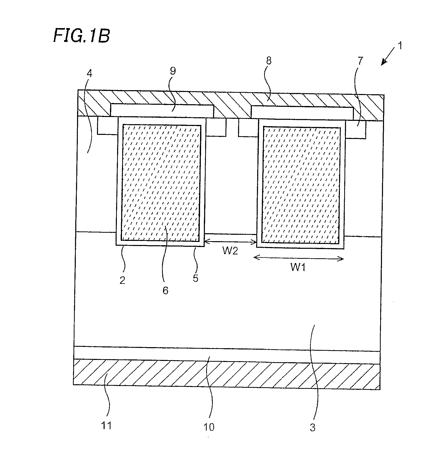
[0027]FIG. 1A shows a plan view of a trench-type IGBT 1 having an NPT structure of the embodiment. FIG. 1B shows a cross sectional view of a section X-X shown in FIG. 1A. Although FIG. 1 shows only two trenches 2 formed in two positions for simplification, actually a plurality of trenches 2 is formed at given intervals so as to form stripes in a plan view.

[0028]The IGBT 1 includes an N− drift layer 3 made of a FZ wafer, a P-type base layer 4 formed on the front surface of the drift layer 3, a plurality of trenches 2 formed from the front surface of the base layer 4 to the drift layer 3, insulated gates configured by forming gate electrodes 6 inside the trenches 2 with gate oxide films 5 being interposed therebetween, N+-type emitter layers 7 formed on the front surface of the base layer 4 adjacent to the insulated gates, an emitter electrode 8 contacting the ...


PUM


Abstract

The invention realizes IGBT having an NPT structure which has a smaller variation in switching characteristics and the like and lower on-resistance. In the IGBT of the invention, by setting a ratio of a width of a trench to an interval between the trenches within a range of 1 to 2, electron current density and a conductivity modulation effect are optimized, a breakdown voltage is secured, a variation in characteristics is minimized, and on-resistance is largely reduced.

Description

CROSS-REFERENCE OF THE INVENTION[0001]This application claims priority from Japanese Patent Application No. 2007-155470, the content of which is incorporated herein by reference in its entirety.BACKGROUND OF THE INVENTION[0002]1. Field of the Invention[0003]The invention relates to an insulated gate bipolar transistor, particularly, an insulated gate bipolar transistor having a trench structure.[0004]2. Description of the Related Art[0005]An insulated gate bipolar transistor is called IGBT, which is one of general high-current switches. FIG. 7A shows a cross-sectional view of a conventional trench-type IGBT having a punch-through (PT) structure.[0006]An IGBT 51 having a PT structure is configured so that an N−-type buffer layer 62 and an N−-type drift layer 53 are formed on a collector layer 60 made of a P+-type semiconductor substrate by epitaxial growth in this order. A P-type base layer 54 is formed on the front surface of the drift layer 53, and a plurality of trenches 52 is for...

Claims


Application Information

Patent Timeline
Patent Type & Authority Applications(United States)
IPC IPC(8): H01L29/70
CPCH01L29/66348H01L29/7397H01L29/73H01L21/18
Inventor OKADA, KIKUO
Owner SANYO ELECTRIC CO LTD
Learn More