
Secure System and Method for Aircraft Emergency Landing

a technology for aircraft and landing gear, applied in the direction of anchoring, alighting gear, anchoring hooks, etc., can solve the problem of large relative displacement between airplane and flat pla

Inactive Publication Date: 2008-12-18
LIU YUEN
View PDF4 Cites 20 Cited by
  • Summary
  • Abstract
  • Description
  • Claims
  • Application Information

AI Technical Summary

Benefits of technology

[0003]The present invention provides a secure system for aircraft emergency landing with disabled undercarriage, which can eliminate impact inertia produced by speed and height and weight in aircraft emergency landing effectively and can protect the aircraft of emergency landing and passengers.

Problems solved by technology

But there will be a biggish relative displacement between airplane and flat plate because of the inertia in descending of airplane.

Method used


Image

  • Secure System and Method for Aircraft Emergency Landing
  • Secure System and Method for Aircraft Emergency Landing
  • Secure System and Method for Aircraft Emergency Landing

Examples


embodiment 1

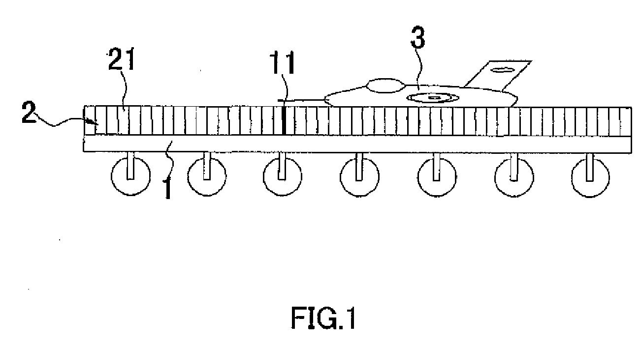
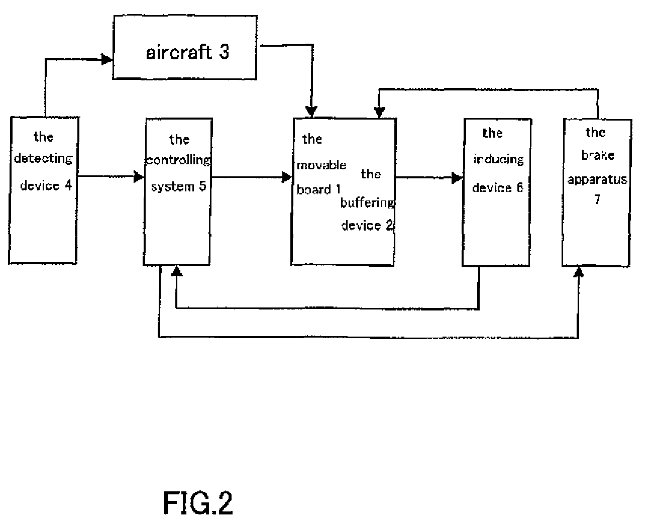
[0031]A secure system for aircraft emergency landing, as shown in FIGS. 1 and 2, comprises a movable board 1, a detecting device 4, a controlling system 5, a buffering device 2 and an inducing device 6. The detecting device 4 detects the landing location and speed of the aircraft 3, and transmits the information to the controlling system 5, which moves the movable board 1 and makes the moving speed and position of the movable board match with the landing speed and position of the aircraft 3. The aircraft 3 lands on the buffering device 2 provided above the movable board 1.

[0032]The buffering device 2 comprises plural independent gas capsules 21 full of antiflaming gas. The gas capsules 21 are erect column, whose height is bigger than the lowest position of the bottom of the aircraft 3 to the airfoil. Plural gas capsules 21 are arranged on the top surface of the movable board 1 regularly, and plural gas capsules 21 lean against each other in turns.

[0033]The movable board 1 comprises ...

embodiment 2

[0036]As shown in FIGS. 3 and 4, the embodiment 2 has difference with the embodiment 1 as follows: the buffering device 2 comprises plural independent gas capsules full of antiflaming gas that is carbon dioxide. The gas capsules 21 are erect column, whose height is bigger than the height from the bottom of the aircraft to the airfoil. Plural gas capsules 21 are arranged on the top surface of the movable board regularly. The top surface of the movable board 1 has a lower front part and a higher back part to increase the resistance of the landing of the aircraft.

[0037]As shown in FIGS. 3 and 4, a secure method for aircraft emergency landing, comprising steps as follows:

[0038]a. detecting landing location and speed of aircraft emergency landing by the detecting device (as shown in FIGS. 3A and 4A);

[0039]b. transmitting the information to the controlling system, and the controlling system moves the movable board and makes the moving speed and position of the movable board match with the...


PUM


Abstract

A secure system and method for aircraft emergency landing are provided. The system includes a movable board, a detecting device, a controlling system and a buffering device. The detecting device detects the landing location and speed, and transmits the information to the controlling system, which moves the board and makes the moving speed and position of the board match with those of landing aircraft according to the detected information. The aircraft will land on the movable board. The buffering device includes plural independent gas capsules full of antiflaming gas provided on the top surface of the movable board. The gas capsules counteract the aircraft's inertia and absorb the impact force quickly. Plural gas capsules are provided independently from each other. Thus, even though the gas capsules hit aircraft first are broken, remain gas capsules still can perform the function of buffering.

Description

FIELD OF THE INVENTION [0001]The invention relates to a secure system and method for aircraft emergency landing.RELATED ART [0002]Chinese patent application number CN00130125 discloses an invention of “A take-off and landing board system for airplane” in 2002.05.15. The invention provides lifting and descending system of airplane, the lifting and descending of airplane is finished under the assistance of a flat plate, said plate provides extra pushing force and braking force, thereby shortens the distance of lifting and descending of airplane. During lifting and descending, and within a certain period of time, the airplane is relatively static on said flat plate, thereby raises the stability of short distance lifting and descending. The invented system can be flexibly used at different site. It can also be used as force landing means with high safety. But there will be a biggish relative displacement between airplane and flat plate because of the inertia in descending of airplane. A...

Claims


Application Information

Patent Timeline
IPC IPC(8): B64F1/02
CPCB64F1/02B64F1/025
Inventor LIU, YUEN
Owner LIU YUEN
Learn More