Multi-Value Modulation/Demodulation Method and Multi-Value Modulation/Demodulation Device

a multi-value modulation and demodulation technology, applied in the field of multi-value modulation/demodulation and multi-value modulation/demodulation devices, can solve the problems of limited frequency band, difficult identification of symbols, and finite resources of electric waves, so as to reduce power consumption, reduce power supply capacity, and increase the efficiency of a plurality of power amplifiers

Inactive Publication Date: 2008-12-11
NIHON UNIVERSITY
View PDF4 Cites 3 Cited by
  • Summary
  • Abstract
  • Description
  • Claims
  • Application Information

AI Technical Summary

Benefits of technology

[0023]The apparatus according to the present invention can operate in a saturation region where efficiencies of a plurality of power amplifiers can be increased, reduce a power consumption, and economically achieve a system configuration based on a reduction in a capacity of a power supply and simplification of thermal control.
[0024]Further, according to the apparatus of the present invention, adding the function of estimating a non-uniform signal arrangement and a superposition error enables reducing an influence of the superposition error and decreasing an error rate, thus providing a great effect in a reduction in a transmission power and in a power consumption.BEST MODES FOR CARRYING OUT THE INVENTION
[0025]The best modes for carrying out the present invention will now be explained hereinafter.
[0026]The present invention has a constitution that does not perform 64-QAM by using two orthogonal amplitude modulators like a conventional technology but performs a vector configuration with respect to outputs from three quadri-phase shift keying units (QPSK) in order to suppress an influence of non-linear characteristics of a power amplifier. When combining the outputs, the outputs having the second and third largest amplitudes are combined by a directional coupler, and then the two signal outputs are superposed and combined in a space by using two different antennas. When combining powers in the space, a gain and a phase involve a superposition error. To reduce an influence of this error, non-uniform signal spatial arrangement 64-QAM is performed on a modulation side, a function that estimates gain and phase errors is provided on a demodulation side to calculate a gain error and a phase error, and a signal spatial arrangement transformed based on the estimated gain error and phase error is calculated with respect to a signal spatial error at the time of modulation, and demodulation is carried out based on this arrangement.
[0027]That is, in 64-valued quadrature amplitude modulation (64-QAM) as one type of multi-level modulation, for example, three or more outputs of quadri-phase shift keying (QPSK) having different amplitude levels are superposed after increasing a power to form M-valued (value that is equal to or above 64 to the 2N-th) QAM, and outputs from respective QPSK-i (i=2 to N) except QPSK-1 having the largest amplitude are combined by a directional coupler after power amplification to obtain a combined signal at the time of formation, and an output from the QPSK-1 having the largest amplitude is spatially superposed on and combined with this combined signal. A signal path of each QPSK unit and a power amplifier includes a variable phase shifter and a variable gain which adjust a gain and a phase, and also includes a divider that inputs input data to each modulator and a data converting function for gray encoding.
[0028]A constitution of an embodiment according to the present invention will now be explained.

Problems solved by technology

Although wireless communication using electric waves plays a considerable role as an access line to a network like mobile communication or broadband communication, electric waves are a finite resource, and a frequency band is limited.
Although the multi-level modulation is a scheme enabling transmission of an information volume including multiple bits by using one symbol, identifying symbols becomes difficult with realization of multiple values, and it is apt to undergo degradation in transmission characteristics due to noise, interferences, and non-linear characteristics of an amplifier.
Therefore, a reception side has a problem that an original signal can not be correctly demodulated and an error rate is increased.
To solve this problem, a transmission power must be increased by an amplifier having an excellent linearity, but there are drawbacks, i.e., a reduction in an efficiency of the amplifier in a region having the excellent linearity, a rise of price of the amplifier with an increase in the transmission power, a high capacity of a power supply, and an increase in price of the system due to, e.g., a countermeasure to heat generation.
However, this case has a drawback that an efficiency of the power amplifier is lowered. FIG. 5 shows a relationship between input-output characteristics and a power efficiency of a typical power amplifier.
Therefore, to obtain a desired output, a power amplifier having a higher output is required, and there is a drawback of a high price of the system due to, e.g., an increase in a power consumption, a high capacity of a power supply, or a need for hardware for a measure against heat.
Meanwhile, as a conventional combining method for combining a plurality of signal waves having different types of information, there is one using a hybrid circuit, but it has a drawback of a reduction in a power combining efficiency due to a theoretical combination loss and a loss of a line of a circuit, and this is also a method using a plurality of antennas to individually combine a plurality of signal waves in a space, but it has a drawback that distances to reception points are different because reference points of the respective antennas are different, and gains (amplitude and phase) consequently become different from each other and a vector after combination varies in dependence on a reception position.
Further, a loss due to a circuit loss also occurs.
Moreover, a loss due to a circuit loss also occurs.
Although two or more types of signal waves can be likewise combined by using a plurality of antennas, in the technology depicted in FIG. 6, the power amplifiers PA has to be operated in regions having an excellent linearity in order to avoid degradation in transmission characteristics due to an influence of non-linear characteristics of the power amplifiers PA, and hence there is a drawback of a reduction in a power efficiency.
Additionally, the conventional combining method using the hybrid circuits depicted in FIG. 7 or FIG. 8 has the drawbacks that the combination loss of 3 dB theoretically occurs in each hybrid circuit, the combination loss is large, and the combination efficiency is decreased as explained above.

Method used


Image

  • Multi-Value Modulation/Demodulation Method and Multi-Value Modulation/Demodulation Device
  • Multi-Value Modulation/Demodulation Method and Multi-Value Modulation/Demodulation Device
  • Multi-Value Modulation/Demodulation Method and Multi-Value Modulation/Demodulation Device

Examples


example 1

[0036]FIG. 17 shows a relationship between an error rate and an energy-noise power density ratio (Eb / No) per bit when each power amplifier is set to an operation point of output back-off 0 dB, 3 dB, 5 dB, or 7 dB in the conventional technology. For reference, linear characteristics as an ideal state are also shown. A reed solomon error correction code and a convolution error correction code having a ½ coding ratio are applied to the characteristics. When the output back-off is increased, transmission characteristics are improved, and the error rate is lowered. However, the output and the power efficiency are simultaneously reduced with the output back-off.

[0037]FIG. 18 shows transmission characteristics with a phase error and a gain error being used as parameters when modulation has a uniform signal arrangement and demodulation does not have a superposion error estimating function in the structure of the modulating section depicted in FIG. 13. The error rate is increased based on th...

example 2

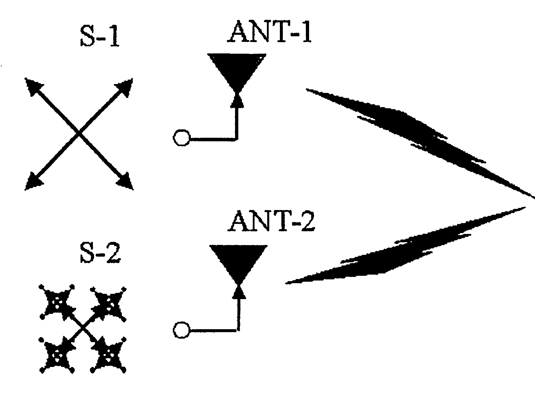
[0038]Although 64-QAM is explained in Example 1, a constitution and others applied to N=4, i.e., 256(=28)−valued QAM can be likewise adopted. In this example, outputs from a QPSK-3 and a QPSK-4 are combined by a 6-dB directional coupler DC-1 to obtain S34. Moreover, an output from a QPSK-2 is coupled with S34 by a directional coupler DC-2 to obtain S234. Additionally, the outputs S1 and S234 are superposed and combined in a space by using two systems of antennas. Therefore, in this embodiment, the same effect as that of 64-QAM can be expected.

example 3

[0039]Meanwhile, as already explained with reference to FIGS. 9 and 10, in the conventional combining method using a plurality of antennas, when the path difference d·sin θ occurs between the lengths of the propagation paths to the reception points in the service area SA due to the distance d between the two antennas, phases of the two signal waves at the reception points in the service area SA are different from each other except for the case where the angle θ=0, and a vector after combination differs depending on each reception point since the two phases differ in dependence on the angle θ. FIG. 22 shows a structure in which a quadri-phase shift keying (QPSK) wave corresponding to FIG. 12 and a 16-valued quadrature amplitude modulation (16-QAM) wave are superposed and combined in a space to realize 64-QAM. FIG. 23 shows a signal spatial arrangement view of 64-QAM (corresponding to 64-QAM on the right-hand side in FIG. 12) in an ideal state where two antenna gains have no phase dif...


PUM


Abstract

Multi-level modulation that is hardly affected by non-linear characteristics of a power amplifier and is equal to or above 64-valued quadrature amplitude modulation (64-QAM) is provided.N (integer equal to or above 3) quadri-phase shift keying (QPSK) outputs having different amplitude levels, i.e., r2=r1·2−(i−1), i=2 . . . N with respect to a maximum amplitude level r1 are superposed after power amplification to form M(=22N)−valued / quadrature amplitude modulation (QAM), and N-1 outputs si except the quadri-phase shift keying QPSK-1 having the maximum amplitude r1 are subjected to power amplification in this formation, then the outputs are combined by a directional coupler to obtain a combined signal, and an output of the quadri-phase shift keying QPSK-1 and the combined signal are transmitted from two systems of antennas to be vectorially superposed and combined in a space. A series / parallel converter is provided before each QPSK unit to divide and input input data of 2N bits, and a variable gain unit and a variable phase shifter adjust a gain and a phase.

Description

TECHNICAL FIELD[0001]The present invention relates to modulation / demodulation used in communication, and more particularly to modulation / demodulation method and apparatus that perform multi-level modulation effective for high-speed communication to realize highly efficient power amplification.BACKGROUND ART[0002]Although wireless communication using electric waves plays a considerable role as an access line to a network like mobile communication or broadband communication, electric waves are a finite resource, and a frequency band is limited. On the other hand, with advancement of an information technology, a demand for high-speed / high-capacity communication is increased, and performing high-speed communication in a limited frequency band is desired. One of the solutions is application of a multi-level modulation scheme. Although the multi-level modulation is a scheme enabling transmission of an information volume including multiple bits by using one symbol, identifying symbols beco...

Claims


Application Information

Patent Timeline
Patent Type & Authority Applications(United States)
IPC IPC(8): H04B1/38H04L27/36H04B7/06H04B7/10H04L27/34
CPCH04B7/0615H04L27/362H04L27/2017H04L27/0008
Inventor TANAKA, MASAYOSHIEGUCHI, TAKUYA
Owner NIHON UNIVERSITY
Why Eureka
Try Eureka