
Generator Control Unit

a technology of generator control and control unit, which is applied in the direction of synchronous generator control, electric generator control, electric propulsion mounting, etc., can solve problems such as degrading voltage responsiveness, and achieve the effect of improving voltage responsiveness

Inactive Publication Date: 2008-12-11
HITACHI LTD
View PDF3 Cites 14 Cited by
  • Summary
  • Abstract
  • Description
  • Claims
  • Application Information

AI Technical Summary

Benefits of technology

The present invention provides a generator control unit and a vehicle drive unit that can improve voltage responsiveness. This is achieved by using a feedback control system that adjusts the DC voltage to maintain a constant rated voltage value, while compensating for fluctuations in the DC voltage caused by changes in the load connected to the battery. The feedback control system includes a PWM signal generation unit and a compensation unit that generates the field voltage command value based on the voltage deviation from the desired value. The compensation unit can be a rotational speed fluctuation compensation unit or a gain compensation unit. The invention also provides a control unit for controlling a generator that compensates for the peak value of the field voltage when the magnetic circuit is in a saturation state. Overall, the invention improves the control of the generator output and ensures a stable voltage output.

Problems solved by technology

In this case, a large voltage feedback gain causes a voltage overshoot, and a small voltage feedback gain degrades voltage responsiveness.

Method used


Image

  • Generator Control Unit
  • Generator Control Unit
  • Generator Control Unit

Examples


Embodiment Construction

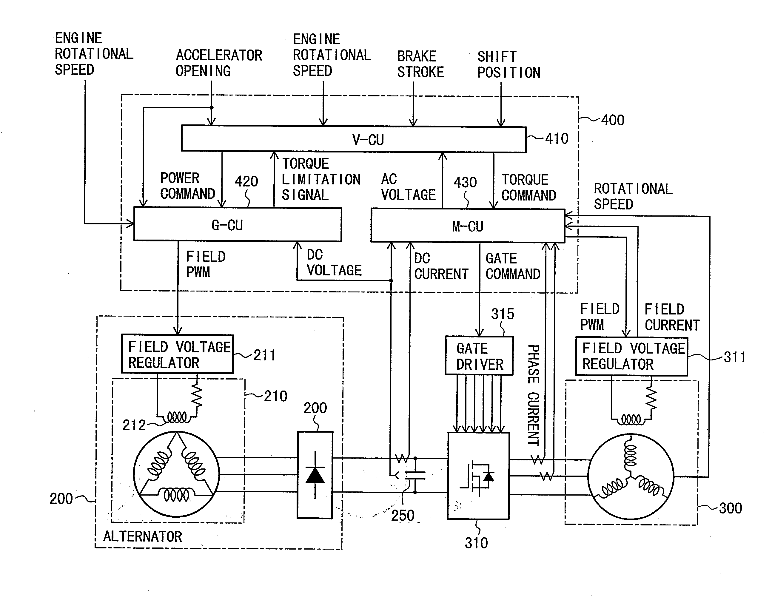
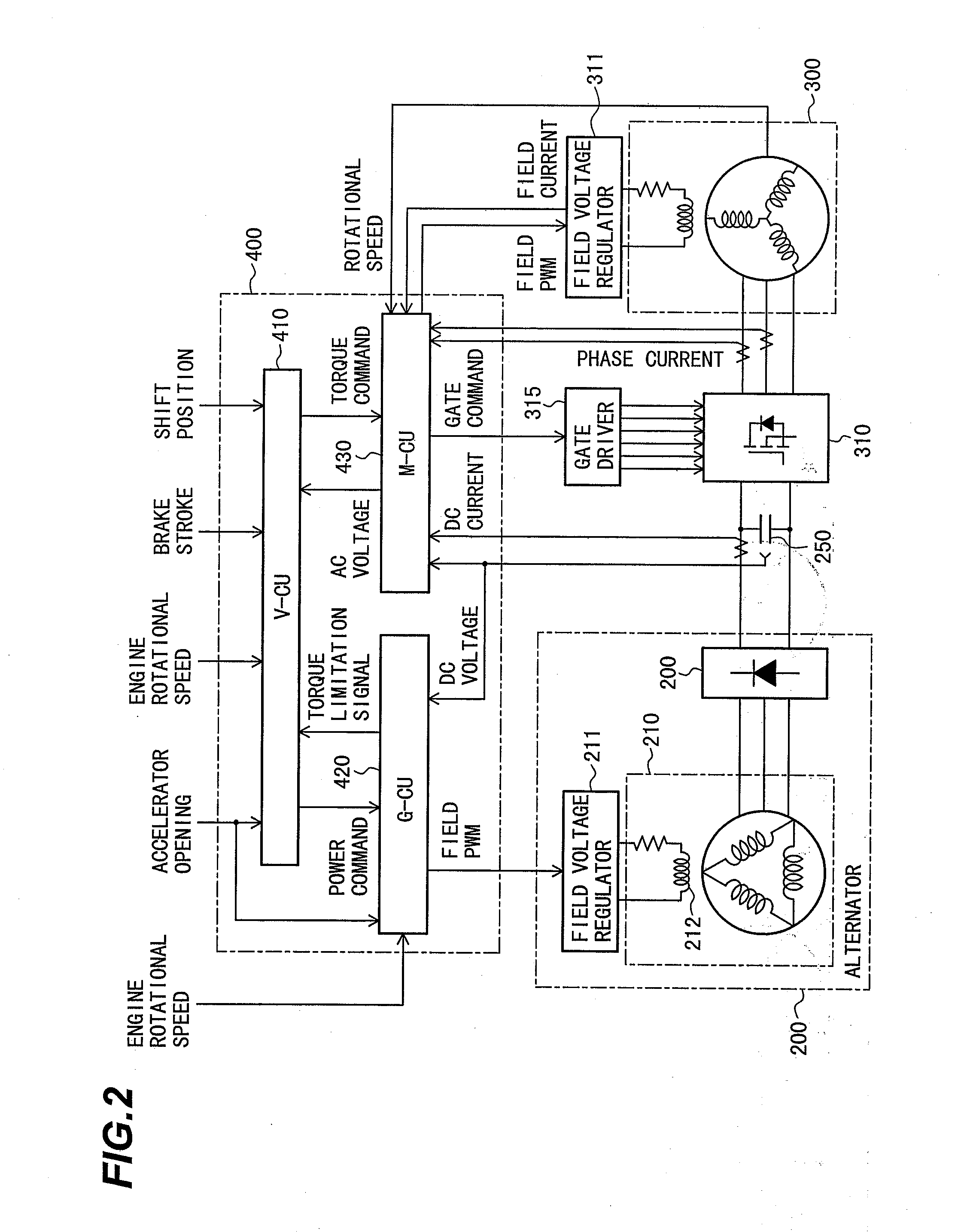
[0037]The configuration and operation of a generator control unit according to an embodiment of the present invention will be explained below with reference to FIGS. 1 to 10.

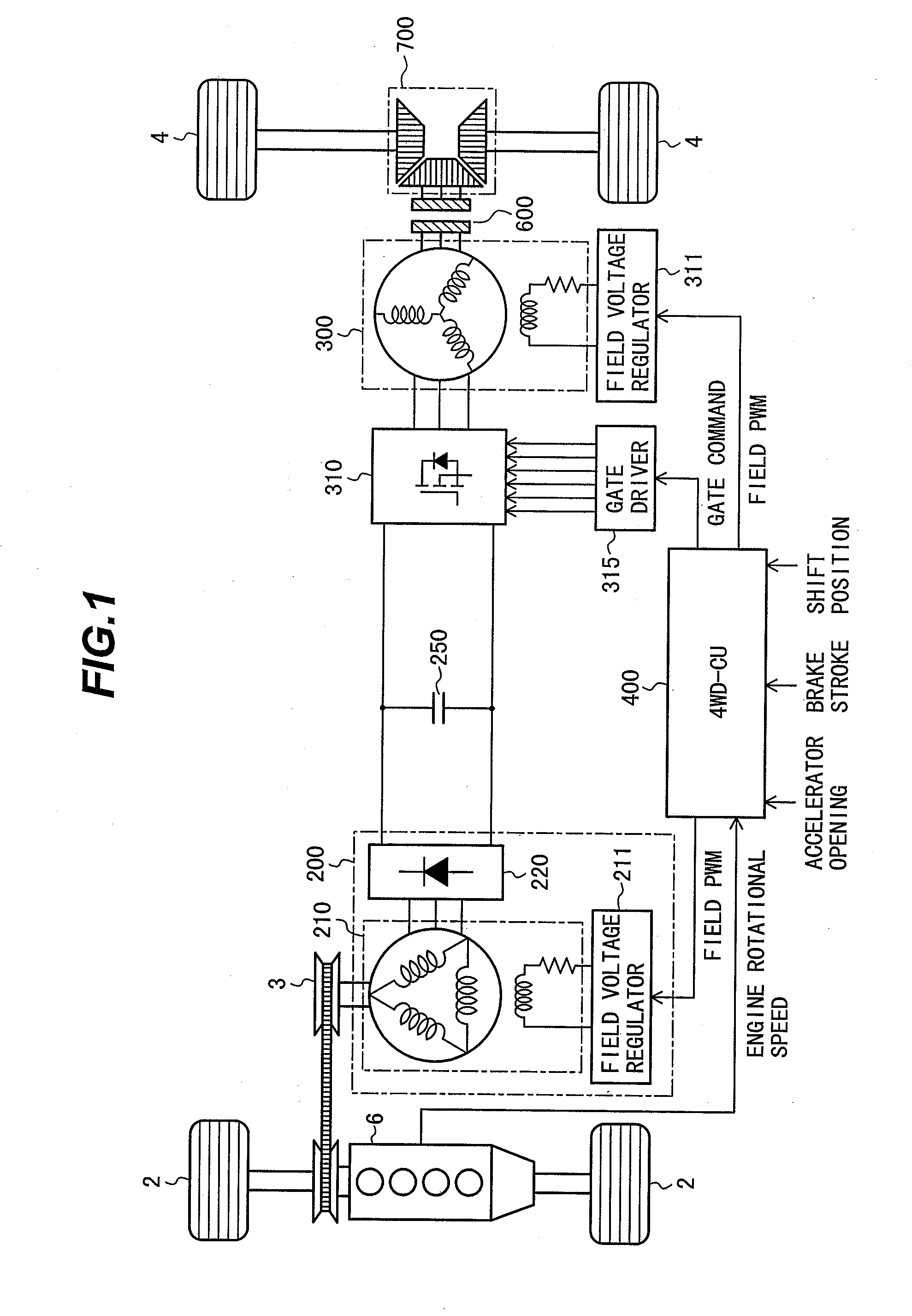
[0038]First of all, the configuration and operation of a four-wheel drive electric vehicle which mounts the generator control unit thereon according to the present embodiment will be explained below with reference to FIG. 1.

[0039]FIG. 1 is a system block diagram showing the configuration of the four-wheel drive electric vehicle which mounts the generator control unit thereon according to an embodiment of the present invention.

[0040]The four-wheel drive electric vehicle shown in FIG. 1 is not provided with a battery that accumulates the output voltage of the alternator between the alternator, which is a power generation unit, and a synchronous motor driven by the output voltage of the alternator. Specifically, the synchronous motor is directly driven by the output voltage of the alternator. With the present embod...


PUM


Abstract

An object of the present invention is to provide a generator control unit having improved voltage response in a system which is not provided with a battery in a DC output unit.In order to control the DC voltage of the DC voltage output terminal in a state where an electric load is connected to the DC voltage output terminal of a power generation unit, a PWM signal generation unit 429 generates a field voltage to be applied to a field winding terminal of the power generation unit. A feedback control unit 422 calculates a field voltage command value to be given to the PWM signal generation unit 429. Further, the feedback control unit 422 includes a PT control unit 423 which calculates a voltage deviation between a DC voltage detection value and a DC voltage command value to generate the field voltage command value through a PI operation based on the voltage deviation. The feedback control unit 422 includes compensation units 424 and 425 which generate a field voltage command value after compensating the output of the PT control unit 423 for the voltage deviation based on input / output transfer characteristics of the generator from the field voltage to the DC voltage.

Description

BACKGROUND OF THE INVENTION[0001]1. Field of the Invention[0002]The present invention relates to a generator control unit which controls a generator.[0003]2. Description of the Related Art[0004]A power generation unit which combines a field winding-type three-phase synchronous generator and a diode rectifier, referred to as an alternator, has conventionally been used as an on-board generator. The alternator is a power generation unit which controls field voltage to control generator output to a desired value. Since the alternator makes it unnecessary to control a generator armature current by means of an inverter or a chopper, it provides a low-manufacturing-cost advantage and has been widely used as a generator for an automobile.[0005]To control an output voltage of the alternator, it is common to perform feedback control on the field voltage through comparison of a detected DC output voltage with a DC voltage command value by use of a PT controller or the like (refer to, for examp...

Claims


Application Information

Patent Timeline
Patent Type & Authority Applications(United States)
IPC IPC(8): H02P9/14B60L9/18H02P9/30H02P101/25H02P101/45H02P103/20
CPCB60K6/46B60L11/14B60L2210/20B60W10/08B60W20/00Y02T10/70Y02T10/6217Y02T10/642Y02T10/7077Y02T10/725H02P9/10B60L50/16Y02T10/62Y02T10/64Y02T10/7072Y02T10/72
Inventor FURUKAWA, KIMIHISAKANEKO, SATORUSUWA, TOKIHITOTAKAMUNE, YUUICHIROUOHNO, SATORUKATSUHAMA, KENTATSUSHIMA, KATSUYO
Owner HITACHI LTD
Learn More