
Adaptive solar concentrator system

a solar concentrator and solar energy technology, applied in the direction of solar heat collectors, solar-ray concentration, moving/orienting solar heat collectors, etc., can solve the problems of low high cost of direct solar electricity generated through photovoltaic (pv) systems, and the effect of reducing the efficiency of diffuse scattered ligh

Inactive Publication Date: 2008-12-04
VARISOLAR
View PDF14 Cites 128 Cited by
  • Summary
  • Abstract
  • Description
  • Claims
  • Application Information

AI Technical Summary

Benefits of technology

[0011]It is an object of the present invention to obviate or mitigate at least one disadvantage of previous solar concentrator systems.

Problems solved by technology

While today's solar thermal technologies are approaching cost parity with heat produced by burning fossil fuels, direct solar electricity generated through photovoltaic (PV) systems is still a factor of two to three times more expensive for sunny locations and four to seven times more expensive for cloudy locations than conventional energy generation in North America, be it from fossil fuels based generators or from nuclear reactors.
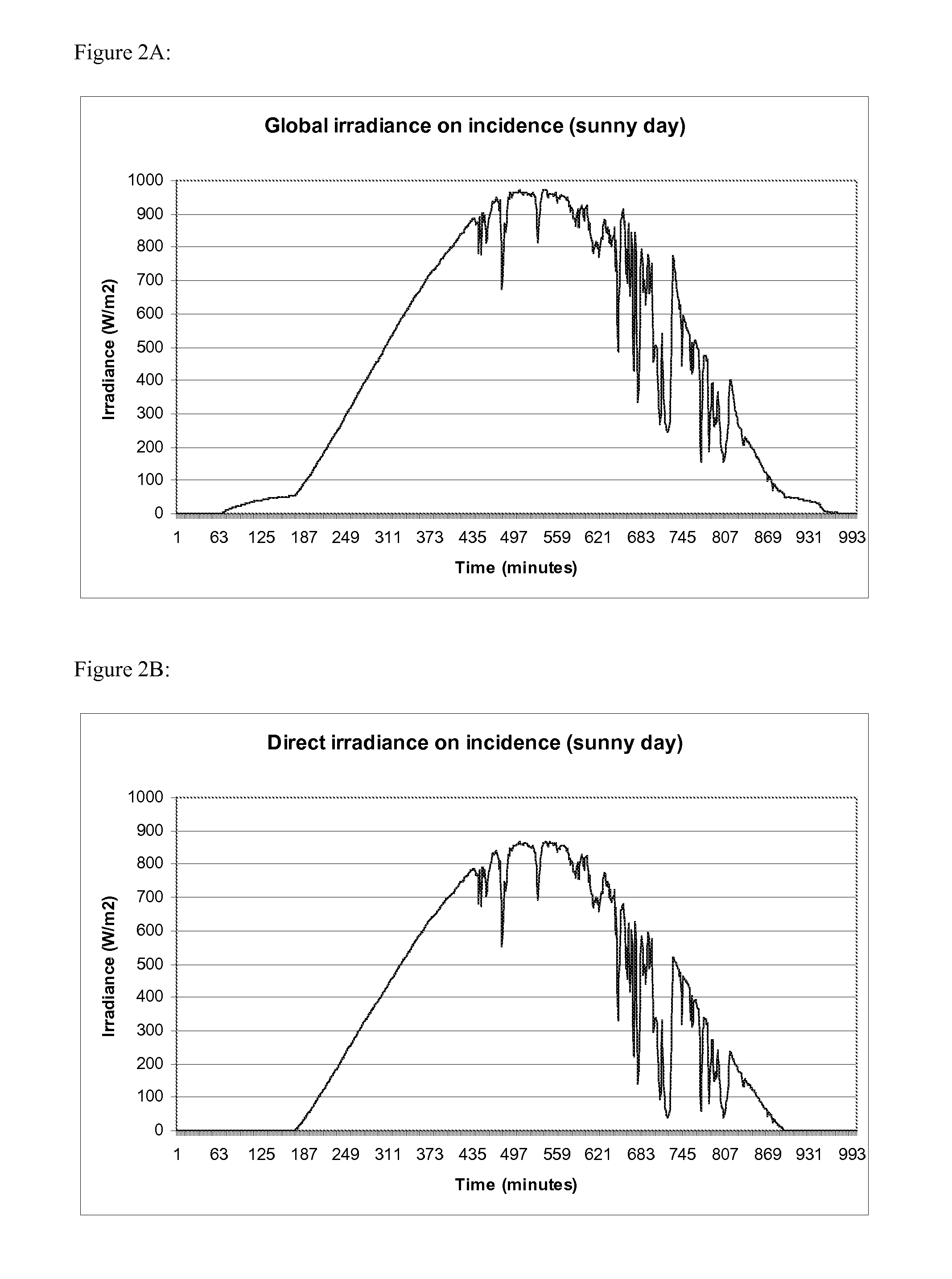
Concentrating solar radiation effectively only works for direct sunlight, while diffuse scattered light is less efficiently and sometimes not even collected at all through the concentrator.
In higher latitude locations, where the climate is generally cloudier, a fixed concentration technology can sometimes prove too expensive, when the additional cost and complexity of concentrating optics, tracking mounts and special solar cells and heat sinks required to withstand higher operating fluxes and temperatures can not be offset by collecting only the concentrated direct irradiation and losing the diffuse contribution.
With a fixed concentrator system, it is not possible to optimize the irradiation impinging on a cell to counterbalance the drop in efficiency in low light or high ambient temperature conditions, or to track weather conditions changing from sunny to cloudy.
However on cold days (or on hot days with low irradiation) the cells' potential is not fully exploited since the concentration ratio could be increased further while still meeting the safe operational limits of the cells, further increasing the collection capabilities of the system.

Method used


Image

  • Adaptive solar concentrator system
  • Adaptive solar concentrator system
  • Adaptive solar concentrator system

Examples


Embodiment Construction

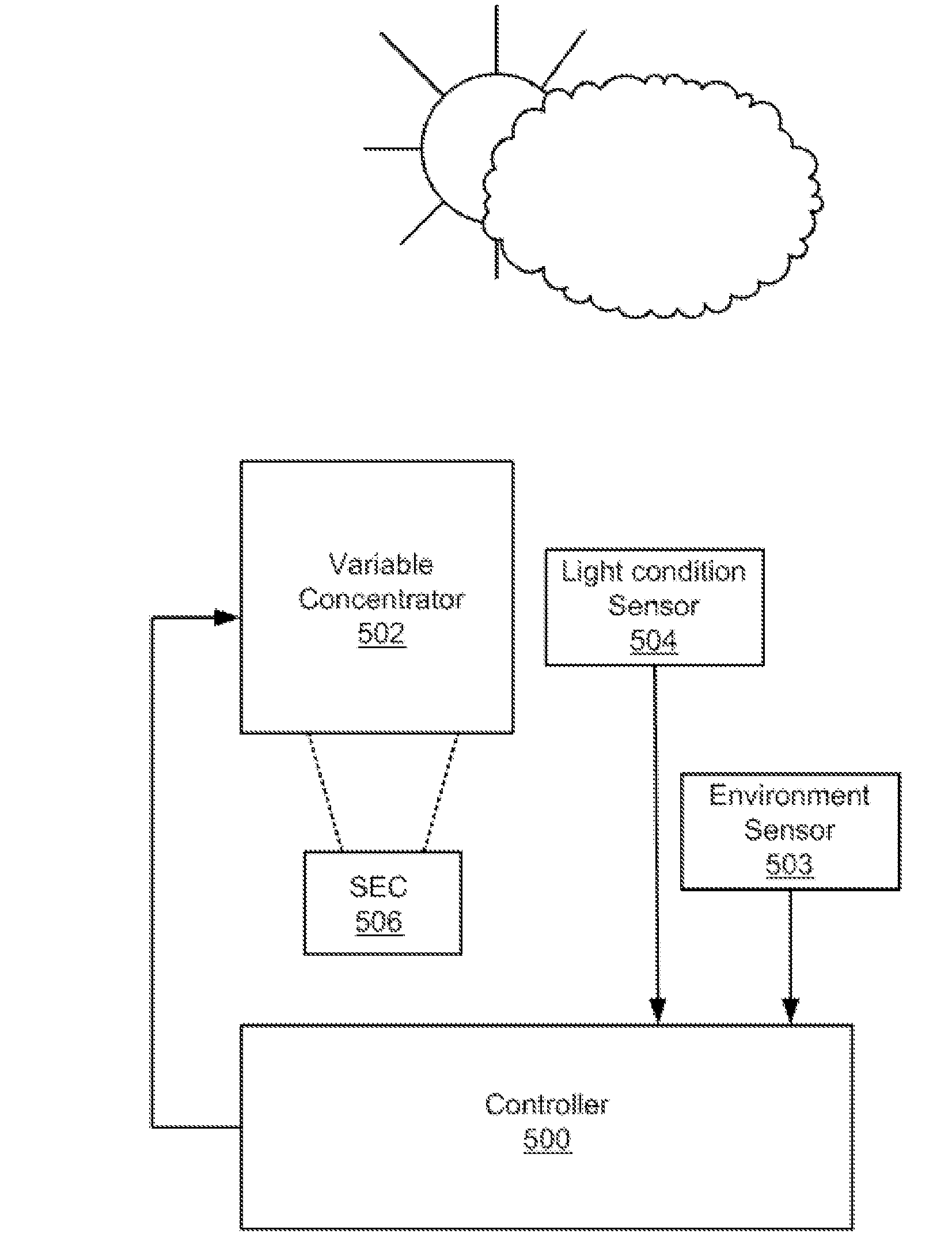
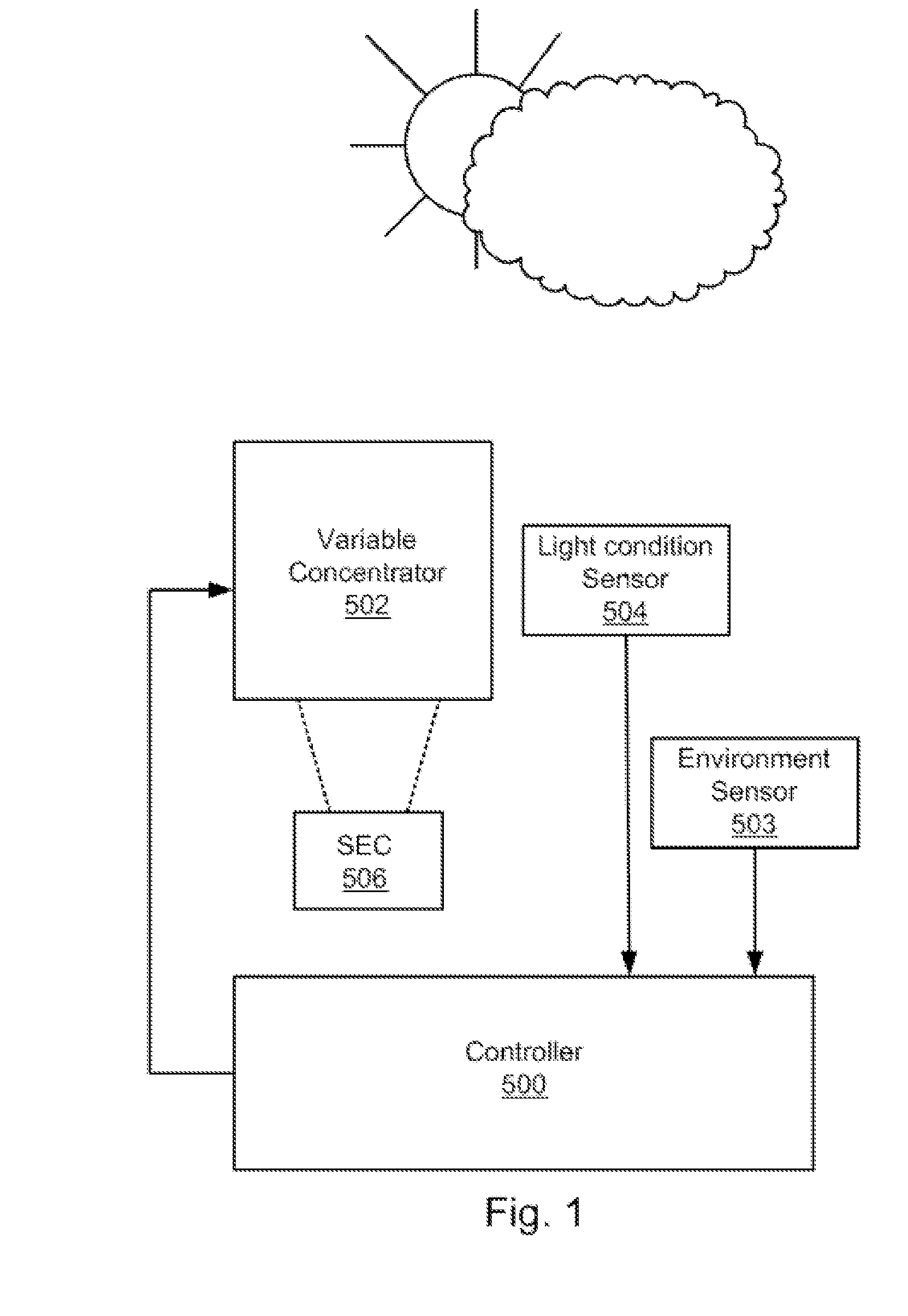
[0053]The sun's radiation reaching the Earth is comprised of “direct” radiation (direct sunlight) and “diffuse” radiation (sun light scattered by the atmosphere, clouds, etc. plus the light reflected by the ground and other objects). The relative amount of direct / diffuse radiation is constantly changing, primarily in response to environmental changes. Generally, the present invention enables the optimization of the energy harvested by a solar energy collector (SEC) under such variable light conditions, especially in response to variable amounts of diffuse versus direct radiation impinging on the SEC. The present invention provides an adaptive solar concentration system and method for controlling the solar irradiance impinging on an SEC. The system comprises a concentrator having a variable concentration ratio and a controller in communication with the concentrator and with a light condition sensor (which can also be referred to simply as a light condition sensor) that provides a lig...


PUM


Abstract

An adaptive solar concentrator system comprising a controller, a solar energy collector and a solar concentrator with variable concentration ratio is disclosed. The concentration ratio of the variable solar concentrator is varied to maximize the energy collection potential of the solar energy collector in response to fluctuations in incoming solar irradiation to best match the optimum operating conditions of the solar collector and to not exceed the maximum operating conditions of the solar collector for long term reliability.

Description

FIELD OF THE INVENTION[0001]The present invention relates generally to solar energy conversion. More particularly, the present invention relates to solar energy concentrators with adaptive concentration ratio.BACKGROUND OF THE INVENTION[0002]With finite amounts of fossil fuels stored in the Earth's crust and negative environmental impact of their use, significant efforts have been spent to develop cost-effective renewable energy solutions. Amongst them, harvesting the sun's radiation energy represents the most environmentally benign and scalable solution. While today's solar thermal technologies are approaching cost parity with heat produced by burning fossil fuels, direct solar electricity generated through photovoltaic (PV) systems is still a factor of two to three times more expensive for sunny locations and four to seven times more expensive for cloudy locations than conventional energy generation in North America, be it from fossil fuels based generators or from nuclear reactor...

Claims


Application Information

Patent Timeline
IPC IPC(8): H01L31/042G05B13/02
CPCG05B15/02Y02E10/52Y02E10/44Y02E10/43Y02E10/47F24J2/06H01L31/0547F24J2/38F24J2/40F24J2/5266F24J2/5417F24J2002/075H01L31/0543F24J2/085F24S30/20F24S23/00F24S50/20F24S30/45F24S2020/23F24S23/31F24S50/00
Inventor DUCELLIER, THOMASVISVANATHA, KUMARDANAGHER, DAVID JOHN
Owner VARISOLAR
Learn More