
Transfer Press Machine

a press machine and transfer technology, applied in the direction of forging/pressing/hammering apparatus, programme control, shape safety devices, etc., can solve the problems of insufficient power supply, frequent change of press motion, and difficulty in accurately setting (inputing) these items in a short tim

Inactive Publication Date: 2008-12-04
AIDA ENG LTD
View PDF6 Cites 17 Cited by
  • Summary
  • Abstract
  • Description
  • Claims
  • Application Information

AI Technical Summary

Benefits of technology

[0018]A first object of the invention is to provide a transfer press machine which can accurately and promptly check interference and can be easily handled. A second object of the invention is to provide a transfer press machine which can automatically, promptly, and accurately optimize the transfer press motion (cycle) in which the SPM is increased while preventing interference.
[0038]Also if a temporary setting of reducing the clamp-unclamp operation moving amount can be automatically performed, the same effects as those above can be achieved. Moreover, limitations to the allowable SPM which may occur when the unclamp operation finish angle and the clamp operation start angle overlap even though the clamp-unclamp operation moving amount is not increased can be automatically eliminated. The same effects (three-dimensional transfer material transfer device) can be achieved even when using a two-dimensional transfer material transfer device.

Problems solved by technology

There has been a tendency to frequently change the press motion, the transfer motion, the shape of various parts, and the like during die tryout in the press production site employing a servomotor-drive press machine.
The previously proposed press machine is not sufficient for satisfying these demands.
However, since these items are technical and require expertise, it is very difficult to accurately set (input) these items in a short time.
This operation requires an additional worker and makes handling very complicated.
Moreover, the results may become inaccurate due to input errors.
This increases the calculation load and increases the processing time.
It is also difficult to determine a specific position at which interference occurs.
Moreover, since the press motion is automatically changed within a range determined in advance in order to automatically prevent interference, it may not be suitable for actual operation.
In addition, it is difficult for a worker other than a skilled person to handle the machine.
Therefore, it is impossible to practically determine the presence or absence of virtual interference before operating the machine in real space.
Moreover, it is very difficult to establish a transfer press motion (cycle) effective for an increase in productivity by increasing the SPM while preventing interference.

Method used


Image

  • Transfer Press Machine
  • Transfer Press Machine
  • Transfer Press Machine

Examples


second embodiment

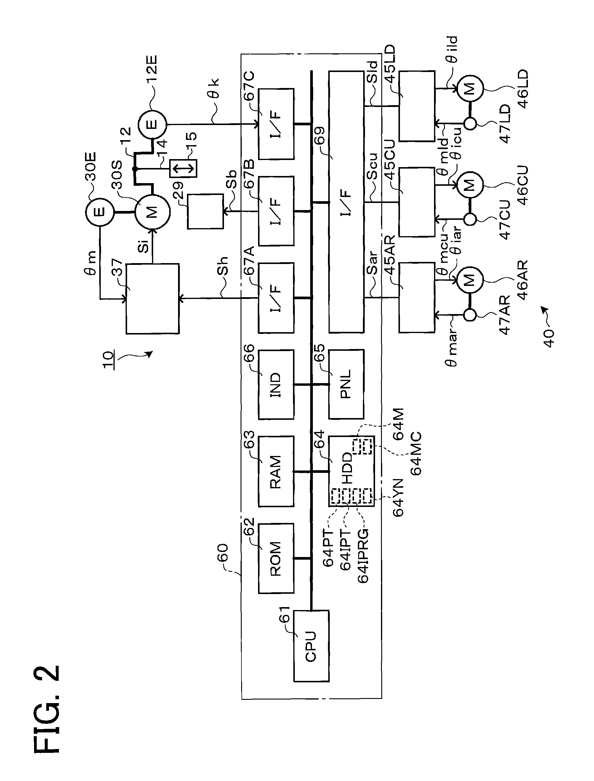
[0082]Each control program characteristic of the invention is stored in virtual control program storage means 64IPRG shown in FIG. 7, and items (e.g. information of BIOS, fixed value, and the like) common to each control program are stored in the ROM 62. This also applies to second virtual interference confirmation target extraction means (61,64) and the like in a second embodiment described later.

[0083]The whole or part of each control program of each means may be stored in the ROM 62, an FRAM, or the like instead of the HDD 64, or may be downloaded from the outside through a data communication line, or may be installed using a medium.

[0084]In regard to drive control of the press machine 10 in real space, the press operation control means (61,64) generates and outputs the target slide position signal Sh to the press control device 37 according to an actual press operation control program stored in actual control program storage means 64MC (area 64MCP) shown in FIGS. 2 and 3 and a p...

first embodiment

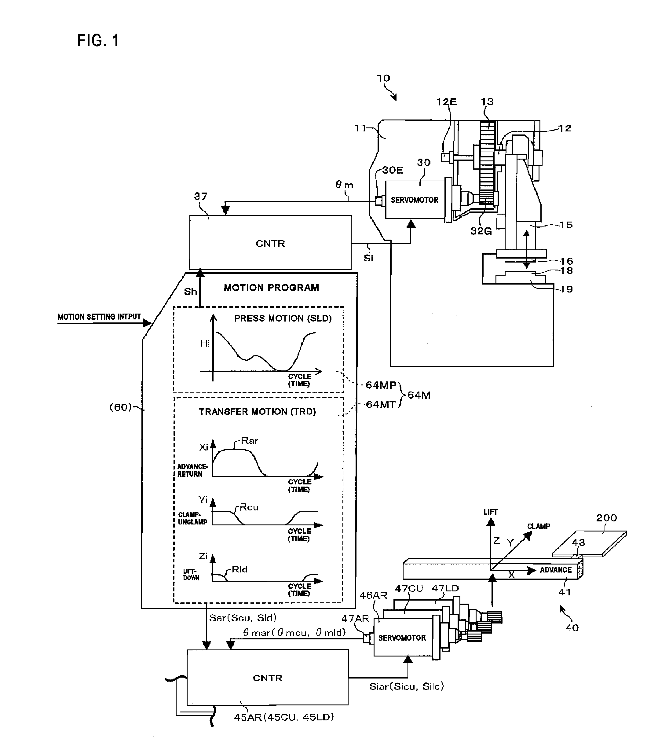
[0134]In the transfer press machine (10,40) when an interference check is requested by key operation of the operation section 65, the interference check device checks (determines) the presence or absence of virtual interference in virtual space according to the procedure shown in FIG. 10.

[0135]Specifically, an initial screen is displayed on the display section 66 (ST10). A plurality of slide motions (SLD) set using the slide motion setting input means (operation section 65) and stored in the press motion storage means 64M (64MP) shown in FIG. 4 and a plurality of transfer motions (TRD) set using the transfer motion setting input means (operation section 65) and stored in the transfer motion storage means 64M (64MT) are also displayed.

[0136]The operator selects the press motion and the transfer motion referring to the displayed information (ST11). In this case, the slide motion (SLD) and the transfer motion (TRD) shown in FIG. 1 or 11 are selected. Since each motion can be selected ...

third embodiment

[0176]In the third embodiment, the means designated as “(61,64)”, such as the press operation control means (61,64) and the transfer operation control means (61,64) which are operated in real space, and the synchronization timing information generation-output means (61,64), the virtual press operation control means (61,64), the virtual transfer operation control means (61,64), and the virtual interference check control means (61,64) which are operated in virtual space, are formed by the HDD 64 which stores respective control programs and the CPU 61 having a program execution function. The program and the like are loaded into the RAM 63 and executed. Specifically, the constituent elements are mainly formed by means of software. Note that the constituent elements may be formed by means of hardware such as a logic circuit.

[0177]This also applies to the first allowable SPM increasing means (61,64), the first virtual interference determination means (61,64), the first increase operation ...


PUM

PropertyMeasurementUnit
angleaaaaaaaaaa
areaaaaaaaaaaa
setting angle theta(st1aaaaaaaaaa

Abstract

A transfer press machine which can accurately and promptly check interference and can be easily handled is provided. The transfer press machine includes an interference check device including: a data-conversion constituent element storage section which stores a press-side data-conversion constituent element and a transfer-side data-conversion constituent element in a state of being placed in virtual space to have the same relative positional relationship as in real space; a virtual press operation control section which causes the press-side data-conversion constituent element to perform a virtual press operation in the virtual space according to a press motion; a virtual transfer operation control section which causes the transfer-side data-conversion constituent element to perform a virtual transfer operation in the virtual space according to a transfer motion; a virtual synchronization timing information generation-output section which generates and outputs virtual synchronization timing information, and a virtual interference determination section which determines whether or not interference occurs between the press-side data-conversion constituent element and the transfer-side data-conversion constituent element during a transfer press cycle.

Description

CROSS REFERENCE TO PRIOR APPLICATION[0001]This is a U.S. national phase application under 35 U.S.C. § 371 of International Patent Application No. PCT / JP2005 / 019934 filed Oct. 28, 2005, and claims the benefit of Japanese Application No. 2004-316801 filed Oct. 29, 2004, both of them are incorporated by reference herein. The International Application was published in Japanese on May 4, 2006 as International Publication No. WO / 2006 / 046717 under PCT Article 21(2).TECHNICAL FIELD[0002]The present invention relates to a transfer press machine including a press machine which can press a material by utilizing the press operation of a slide and a material transfer device which can transfer a material to the press machine, the press machine and the material transfer device being disposed in real space to have a specific relative positional relationship, and can press the material transferred during a transfer press cycle in which the press operation and the transfer operation are synchronized....

Claims


Application Information

Patent Timeline
Patent Type & Authority Applications(United States)
IPC IPC(8): B21J11/00
CPCB21D43/05B30B15/14G05B19/4061B30B15/146B30B15/26B30B13/00B30B15/00B30B15/16
Inventor KANEKO, SOTOYUKIHOSOYA, HIROSHIKUBOE, KAZUHIRO
Owner AIDA ENG LTD
Learn More