
Access Assembly With Ribbed Seal

Inactive Publication Date: 2008-11-27
TYCO HEALTHCARE GRP LP
View PDF41 Cites 26 Cited by
  • Summary
  • Abstract
  • Description
  • Claims
  • Application Information

AI Technical Summary

Benefits of technology

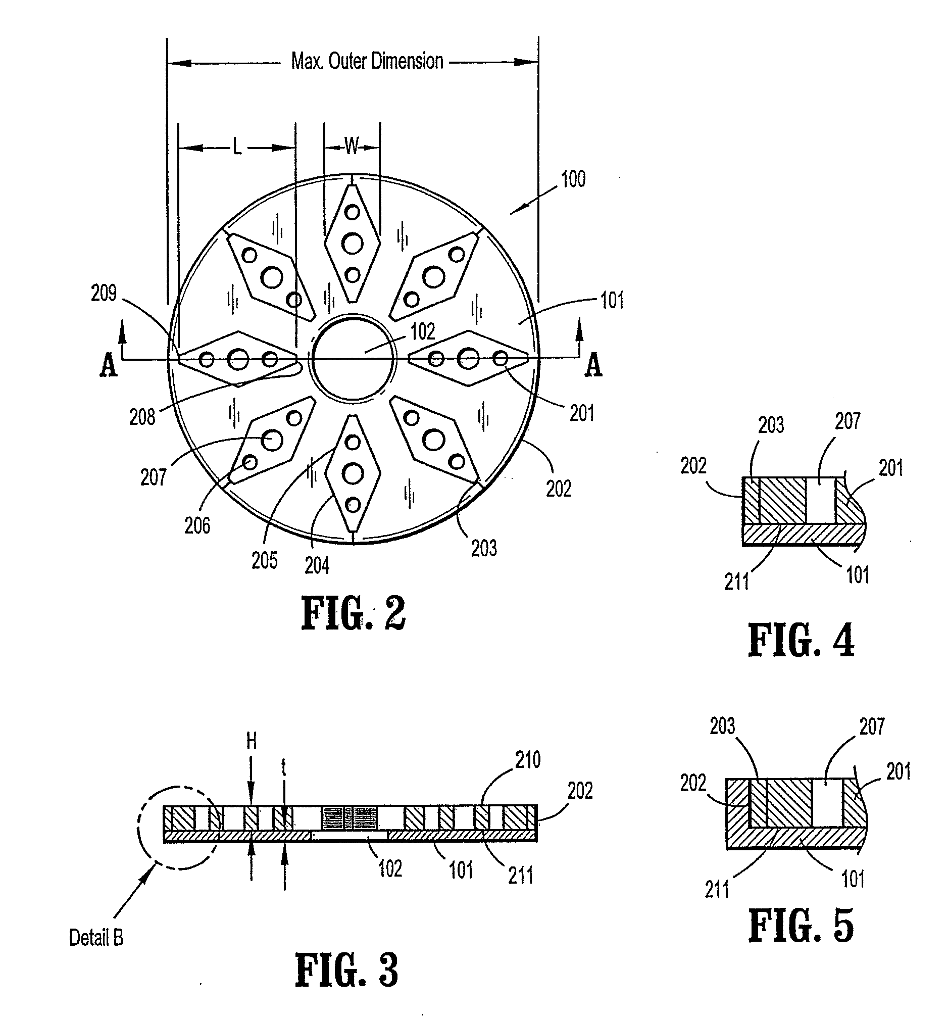
[0011]In other embodiments, the seal may include a radial array of ribs extending inwardly from the annular element which may cooperate to urge the instrument into alignment with the seal axis. Furthermore, the seal may be a septum seal having a generally planar configuration with an aperture for passage of the instrument. The rib or ribs included on the seal may be tapered such that the width decreases toward the seal axis, or the rib or ribs may be generally diamond shaped such that the width decreases toward the annular element as well as toward the seal axis. Openings may be included on a rib to enhance its flexibility. The ribs may include a free end which is adjacent to the passageway through the first elastomeric member, and the free end may be substantially spaced from the passageway. An alternative rib shape involves a fork such that a first leg of the rib extends inwardly from the annular element and second and third legs extend inwardly from the first leg. The second and third legs of a forked rib may be spaced from one another and include portions which are generally parallel.

Problems solved by technology

As discussed above, a flapper valve, a duckbill valve or other type of cannula seal typically will not prevent fluid losses once an instrument is in place within the cannula.
On the other hand, many of these design considerations compete with one another.
The increased surface area in contact with the instrument will enhance the sealing characteristics, but at the same time will adversely affect the insertion and glide forces.
An instrument seal designed to be extremely flexible in order to minimize insertion and glide forces may be ineffective in providing radial support to an instrument.

Method used


Image

  • Access Assembly With Ribbed Seal
  • Access Assembly With Ribbed Seal
  • Access Assembly With Ribbed Seal

Examples


Embodiment Construction

[0021]The present disclosure contemplates the introduction into a person's body of all types of surgical instruments including clip appliers, graspers, dissectors, retractors, staplers, laser fibers, photographic devices, endoscopes and laparoscopes, tubes, and the like. All such objects are referred to herein generally as “instruments.” In the drawings and in the description which follows, the term “proximal,” as is traditional, will refer to the direction toward the operator or a relative position on the surgical device or instrument which is closer to the operator, while the term “distal” will refer to the direction away from the operator or relative position of the instrument which is further from the operator.

[0022]Referring initially to FIG. 1, the ribbed seal 100 of the present invention is shown as a component of cannula assembly 10. The distal end (not shown) of cannula 12 is intended to be inserted into a body cavity through a small cut made in the skin to provide a portal...


PUM


Abstract

A ribbed seal for use in endoscopic surgery is intended to be incorporated into a cannula assembly to limit the escape of insufflation gasses from a body cavity by forming a fluid-tight seal around an instrument inserted through the cannula assembly. The ribbed seal includes a relatively flat, disk shaped elastomeric overmold portion having a central aperture sized slightly smaller than the instrument such that the aperture must expand to accommodate the instrument. Molded together with the elastomeric overmold is an array of slender ribs disposed about the aperture. The ribs are designed to be relatively flexible under lateral loads. This allows the seal to bend easily as the surgical instrument is inserted through the aperture thereby maintaining a low insertion and glide force. On the other hand, the ribs are designed to be relatively rigid when loaded axially. This rigidity provides robust radial support for the instrument inserted through the center of the array of ribs. The seal performs a centering function for the instrument due to its combined elasticity and stiffness. Finally, the seal also allows for an instrument to be removed easily while maintaining the required atmospheric integrity.

Description

CROSS REFERENCE TO RELATED APPLICATION[0001]The present application claims the benefit of and priority to U.S. Provisional Application Ser. No. 60 / 931,253 filed on May 22, 2007, the entire contents of which are incorporated herein by reference.BACKGROUND[0002]1. Technical Field[0003]The present disclosure relates generally to a seal for use in endoscopic surgery adapted to maintain a fluid-tight connection about an instrument inserted through a cannula. In particular, the disclosure relates to a seal member having elasticity and rigidity characteristics which facilitate its effective use.[0004]2. Background of Related Art[0005]Minimally invasive surgical procedures are performed throughout the body and generally rely on obtaining access to an internal surgical site through a small incision made in the skin of a patient. A cannula is a narrow tube, typically 5 to 13 mm in diameter, which is partially inserted into the small incision in the skin to hold the incision open. The cannula ...

Claims


Application Information

Patent Timeline
IPC IPC(8): A61M39/06
CPCA61B17/3421A61B17/3498A61B2017/3464
Inventor BROCKMEIER, OIVINDJUDSON, JARED ALDENFOCHT, KENNETH ALLEN
Owner TYCO HEALTHCARE GRP LP
Learn More