
Branched catheter tip

Inactive Publication Date: 2011-03-24
ANGIODYNAMICS INC
View PDF110 Cites 5 Cited by
  • Summary
  • Abstract
  • Description
  • Claims
  • Application Information

AI Technical Summary

Benefits of technology

[0002]The present invention is directed to venous access devices that include branches at the distal end to enhance device flexibility and to minimize the risk of fibrin sheath adherence and encrustation by blood or other bodily fluids.

Problems solved by technology

Additionally, the implanted portion of the catheter may be susceptible to fibrin sheath adherence and encrustation, which may reduce the mobility of the implanted portion.

Method used


Image

  • Branched catheter tip
  • Branched catheter tip
  • Branched catheter tip

Examples


Embodiment Construction

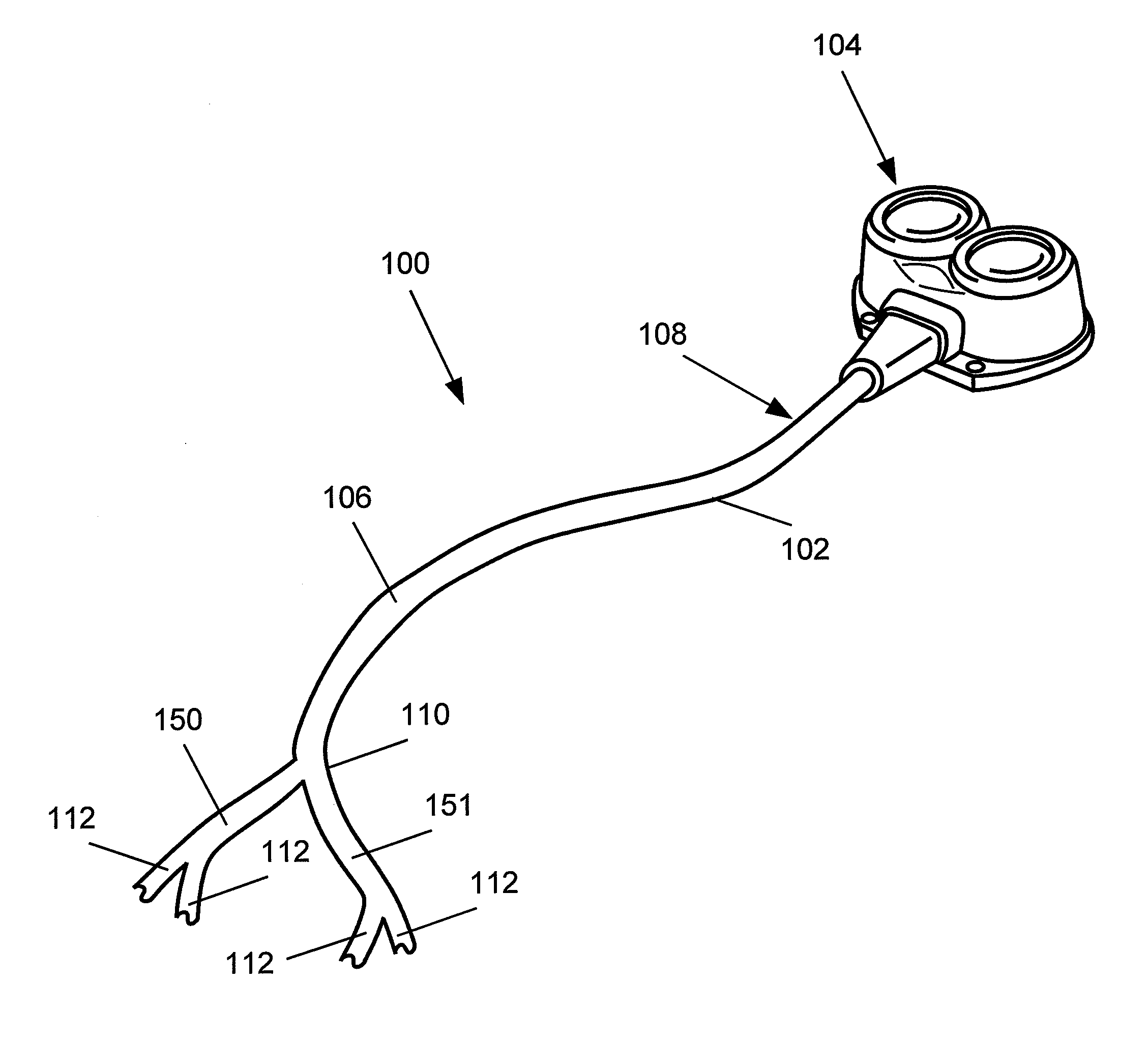
[0010]The present invention may be further understood with reference to the following description and the appended drawings, wherein like elements are referred to with the same reference numerals. The present invention relates to devices for the transfer of fluids to and from a target structure within a patient's body over an extended period of time. In particular, exemplary embodiments of the present invention describe a venous access device that includes a branched distal tip for improved mobility, flexibility and flow.

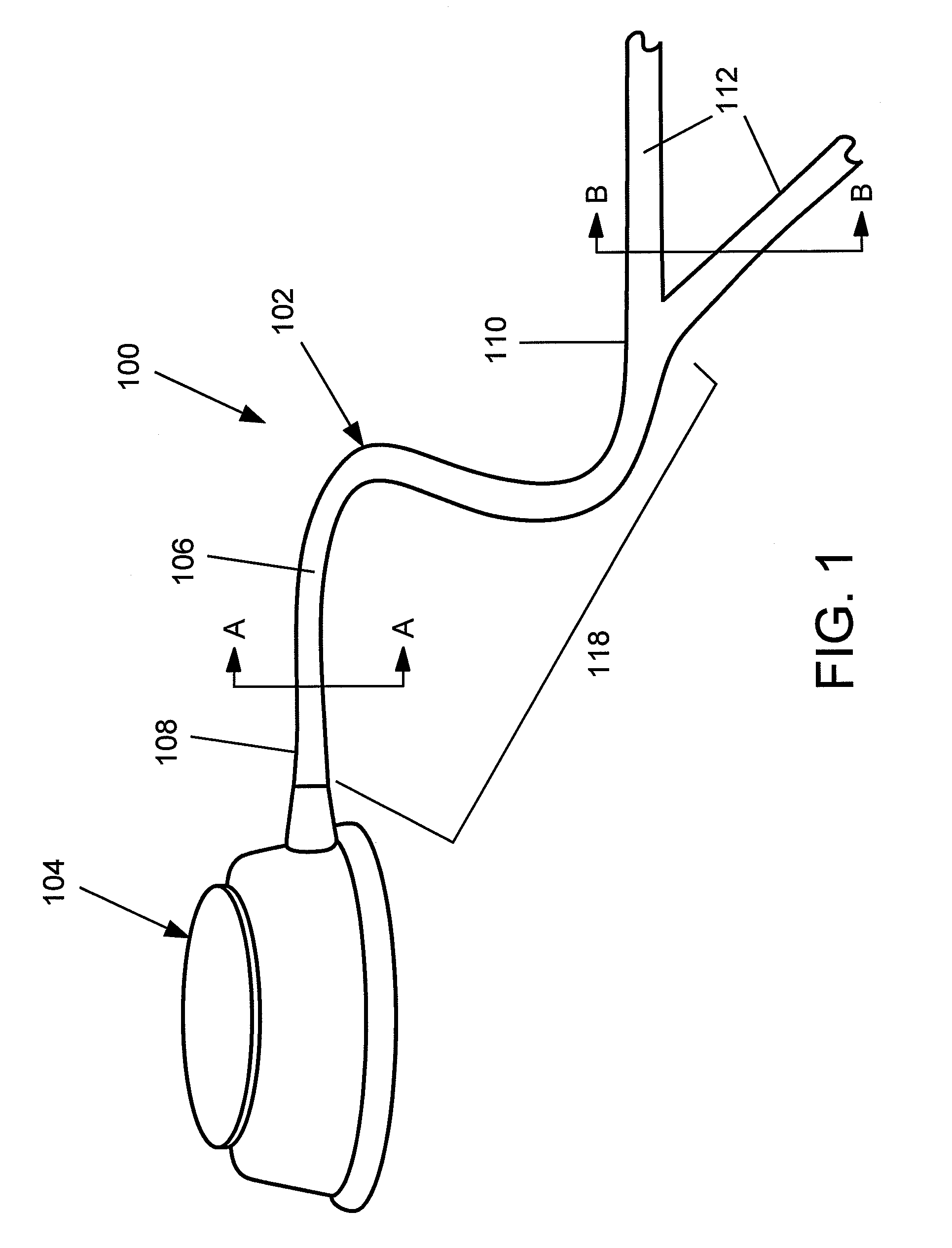
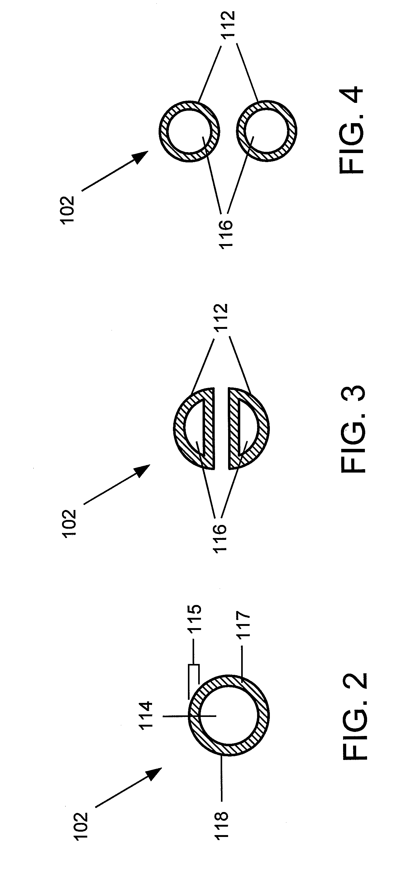
[0011]As shown in FIGS. 1-3, a venous access device 100 according to an exemplary embodiment of the present invention comprises an indwelling catheter portion 102 a proximal end 108 of which is connected to a port device 104. It will be understood by those of skill in the art that, although the device 100 is described as a port catheter system with a port device 104, the device 100 may be any venous access device, such as PICCs, central venous catheters (CVCs), dial...


PUM


Abstract

A venous access device comprises a catheter portion extending longitudinally from a proximal end to a distal end, the flexible shaft defining a lumen therein in combination with a plurality of branches separated from one another and extending distally from the flexible shaft.

Description

BACKGROUND[0001]Venous access devices (VADs) include ports and indwelling catheters such as peripherally inserted central catheters (PICCs) that include flexible tubes used to supply fluids to internal body structures (e.g., nutrients, medications, blood products, etc.) over extended periods of time. Indwelling catheters may also be used to aspirate fluids such as blood from the patient for diagnostic procedures or to drain fluids for other therapeutic purposes. An indwelling catheter may, for example, include a proximal portion extending outside the skin or inside a pocket under the skin, while a distal tip extends through the body often along a tortuous path to enter a target body structure—e.g., the superior vena cava. To reduce trauma to tissue along this path, indwelling catheters are often made smaller in diameter, resulting in reduced flow rates. Additionally, the implanted portion of the catheter may be susceptible to fibrin sheath adherence and encrustation, which may reduc...

Claims


Application Information

Patent Timeline
IPC IPC(8): A61M25/00
CPCA61M1/285A61M1/3653A61M2025/0037A61M25/0054A61M2025/0031A61M25/003A61M1/3659
Inventor LAREAU, RAYMOND
Owner ANGIODYNAMICS INC
Learn More