
Refrigerant service port valve for air conditioners

Active Publication Date: 2008-11-27
A S TRUST & HLDG
View PDF22 Cites 20 Cited by
  • Summary
  • Abstract
  • Description
  • Claims
  • Application Information

AI Technical Summary

Benefits of technology

[0011]In use, a first refrigerant service port valve is placed inline in the high pressure side of the air conditioning system, which may be an automotive air conditioning system, and a second refrigerant service port valve is placed inline in the low pressure side of the air conditioning system. The valves are oriented so that the flame arrestor faces the passenger compartment of the vehicle (in the outlet side of the high pressure valve or the inlet side of the low pressure side) to reduce the risk of fire in the event of an accident that severs or damages the tubing, the check valve preventing flashback or backflow of refrigerant. In normal use, refrigerant circulates in the air conditioning system through the unobstructed main fluid conduit.

Problems solved by technology

However, it was discovered that the use of CFC's over the years has caused ozone layer depletion, an unquestionably negative impact on the global environment.
While HC refrigerants have been approved for use in industrial process refrigeration, the U.S. EPA has not approved its use in automotive refrigerant systems, and its use as a direct replacement for CFC-12 refrigerant in automotive systems is illegal.
Nevertheless, the use of flammable hydrocarbon refrigerants in automotive refrigerant systems is illegal under the laws of many of the states of the United States.
In part, safety concerns have revolved around the risk of leakage into the passage compartment of vehicles in the event of a crash and possible flashback and ignition, with the resulting risk of explosion and fire.

Method used


Image

  • Refrigerant service port valve for air conditioners
  • Refrigerant service port valve for air conditioners
  • Refrigerant service port valve for air conditioners

Examples


Embodiment Construction

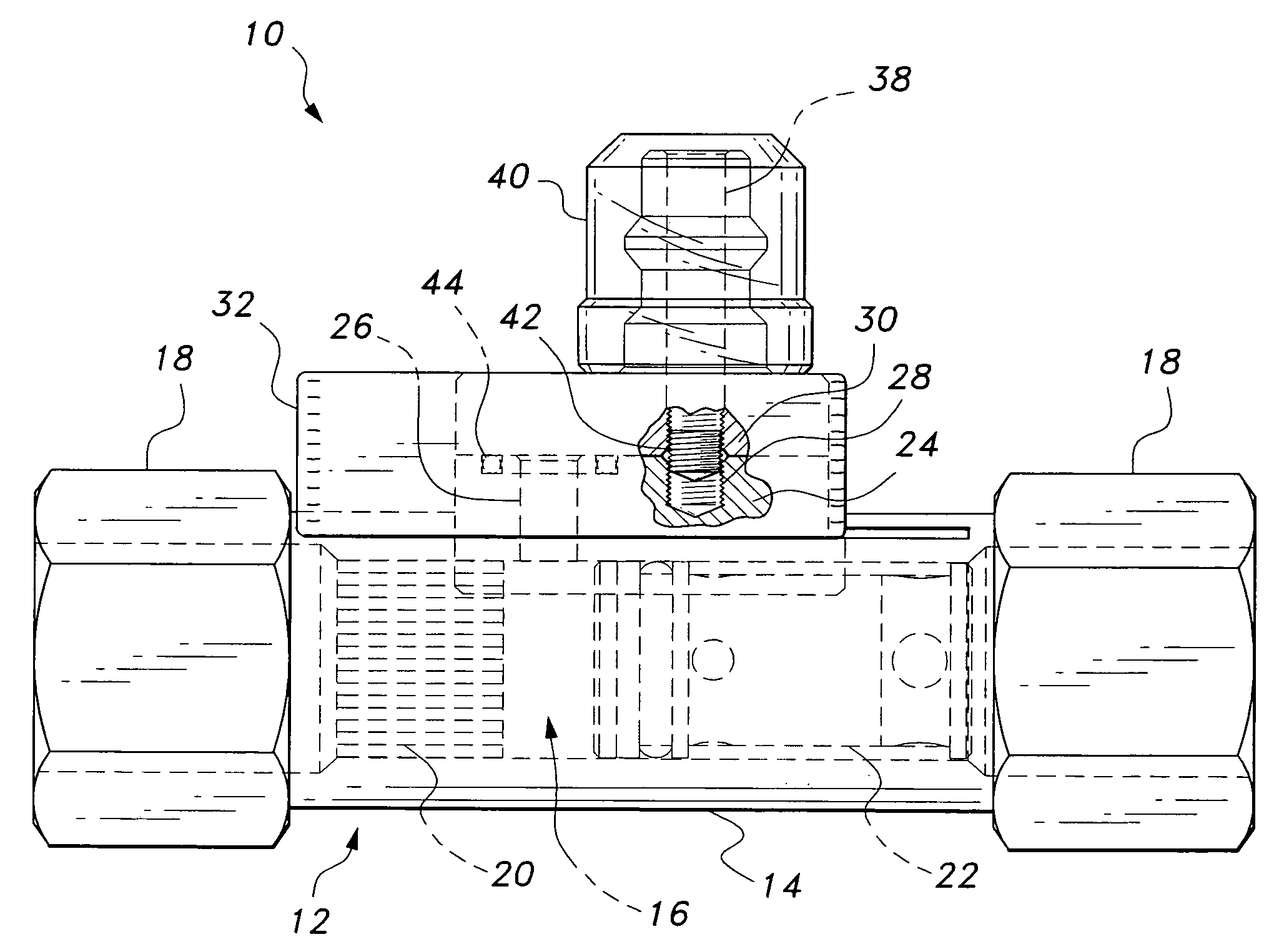
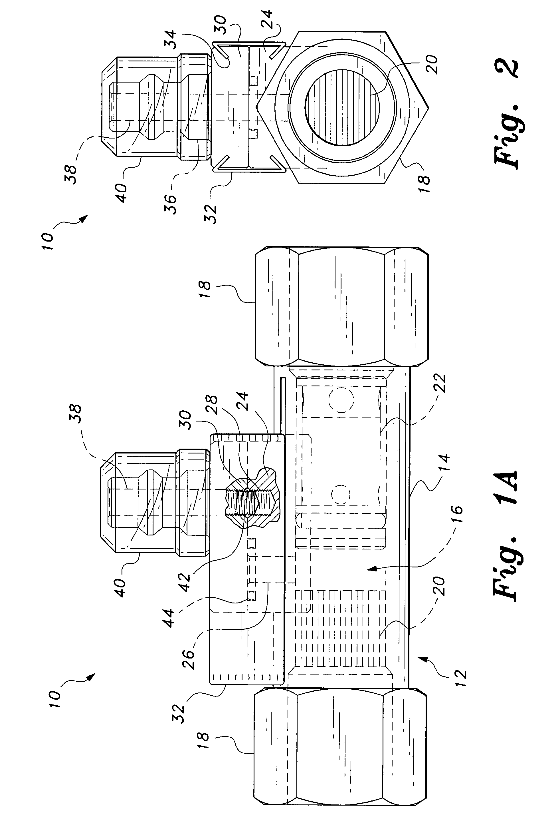
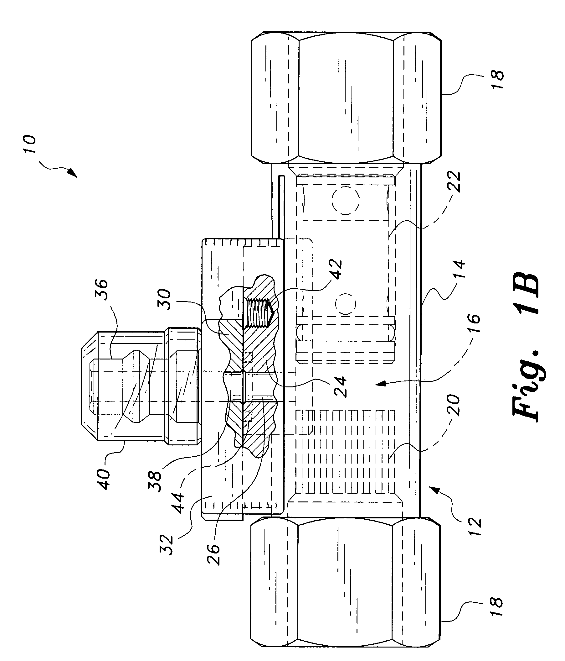
[0019]The present invention is a refrigerant service port valve, designated generally as 10 in the drawings, for use in air conditioning systems that use a hydrocarbon refrigerant, such as HCR188C. The valve 10 will be described as it might be used in an automotive air conditioning system, particularly to retrofit automotive air conditioning systems that were originally designed for HFC-134a and other legacy cooling systems. However, it will be understood that the valve 10 may be used in other air conditioning and refrigeration systems where hydrocarbon refrigerants may be used.

[0020]Referring to FIGS. 1A, 1B, and 2, the valve 10 is a three-way slider valve having a valve body 12 that includes an elongated section of pipe 14 defining a main fluid conduit 16. The pipe 14 may be equipped with compression fittings 18 at opposite ends adapted for inserting the valve 10 inline into either the high pressure or low pressure side of the cooling system. Alternatively the pipe 14 may be equip...


PUM


Abstract

The refrigerant service port valve for air conditioners has a valve body defining a main fluid conduit adapted for insertion into a coolant line using compression fittings at opposite ends of the conduit. A pedestal is mounted on the exterior conduit wall. The pedestal has a bore therethrough forming a lower service passage that enters the main fluid conduit, and an internally threaded blind bore parallel to the lower service passage. A slider is mounted on the pedestal, the slider having a male quick connect fitting defining an upper service passage. The upper service passage may be aligned with the lower service passage in an open position to service the system, or the slider may be moved to align the upper service passage with the blind bore to access a setscrew, which is raised partially into the upper service passage to lock the valve in a closed position.

Description

BACKGROUND OF THE INVENTION[0001]1. Field of the Invention[0002]The present invention relates to the valves used in air conditioning systems, and more particularly to a refrigerant service port valve for air conditioners used to convert or “retrofit” legacy refrigeration systems to the use of environmentally more desirable refrigerants having different operating characteristics, in particular, the refrigerant known as HCR188C® (HCR188C is a registered trademark of A.S. Trust & Holdings Inc. of Saipan, M.P.).[0003]2. Description of the Related Art[0004]Chlorofluorocarbons (CFC's), such as dichlorodifluoromethane and monochlorodifluoromethane, were in heavy usage as a refrigerant for use in automotive air conditioners for many decades. The historical dominance of the CFCs had been, in part, due to their advantageous safety features such as incombustibility, high stability, and lower toxicity. However, it was discovered that the use of CFC's over the years has caused ozone layer deplet...

Claims


Application Information

Patent Timeline
IPC IPC(8): F16K1/12F25B45/00
CPCF25B45/00Y10T137/87941Y10T137/6137Y10T137/7504Y10T137/88062
Inventor MARUYA, RICHARD H.WHITMYRE, GEORGE M.
Owner A S TRUST & HLDG
Learn More