
Fuel processor for use in a fuel cell system

a fuel cell and processor technology, applied in the field of fuel processors, can solve the problems the integration of the given cell stack, and the waste of energy of thermal inefficiencies in the fuel cell system

Inactive Publication Date: 2008-11-27
ULTRACELL ACQUISITION
View PDF10 Cites 53 Cited by
  • Summary
  • Abstract
  • Description
  • Claims
  • Application Information

AI Technical Summary

Problems solved by technology

As such, it can only be integrated with a given cell stack.
The fuel processor is also a separate device, thermally and fluidically, and requires substantial fluidic and gaseous manifolding and thermal insulation, which adds to the fuel cell system volume and mass.
Thermal inefficiencies in a fuel cell system wastes energy and undesirably requires more fuel to be consumed and carried.

Method used


Image

  • Fuel processor for use in a fuel cell system
  • Fuel processor for use in a fuel cell system
  • Fuel processor for use in a fuel cell system

Examples


Embodiment Construction

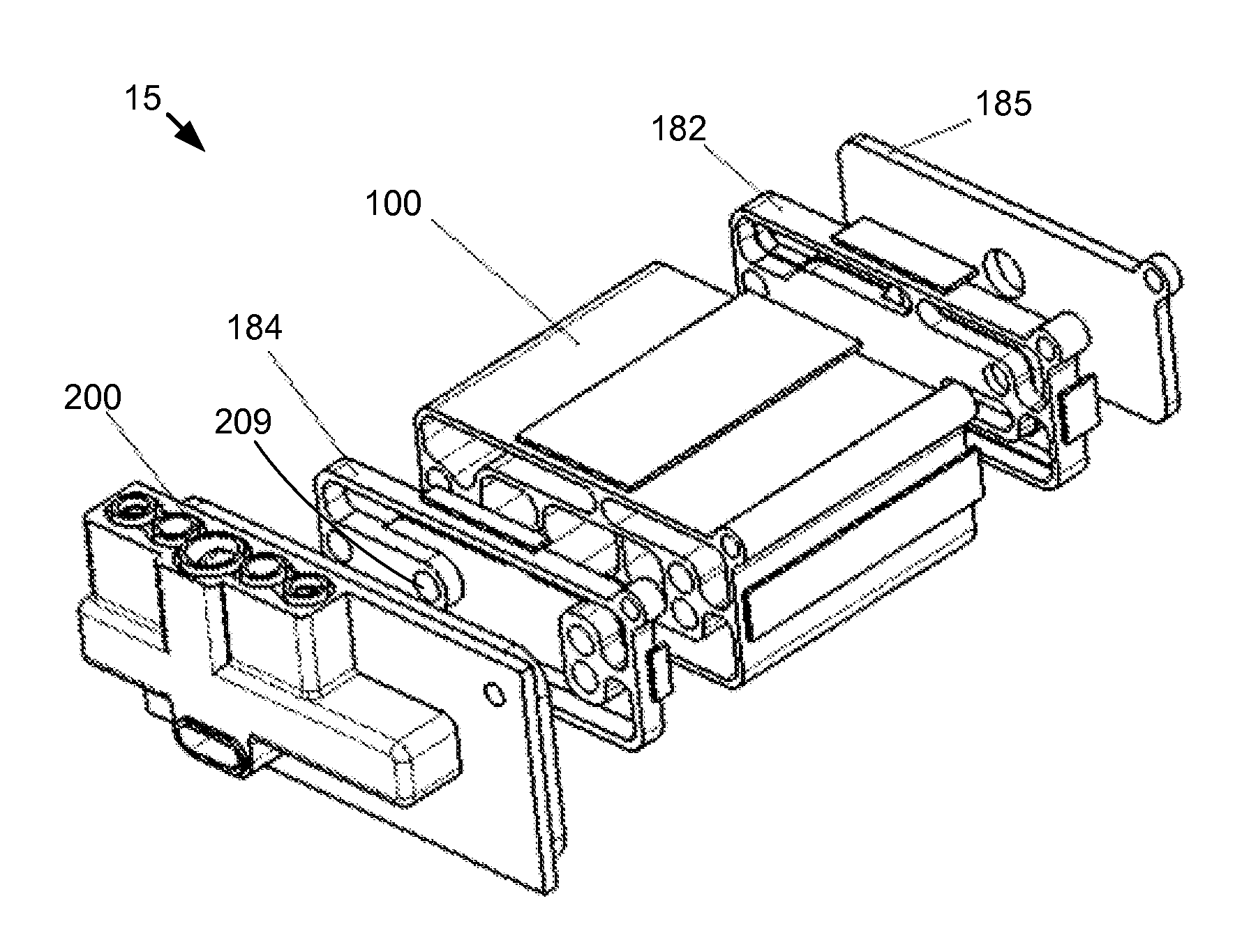
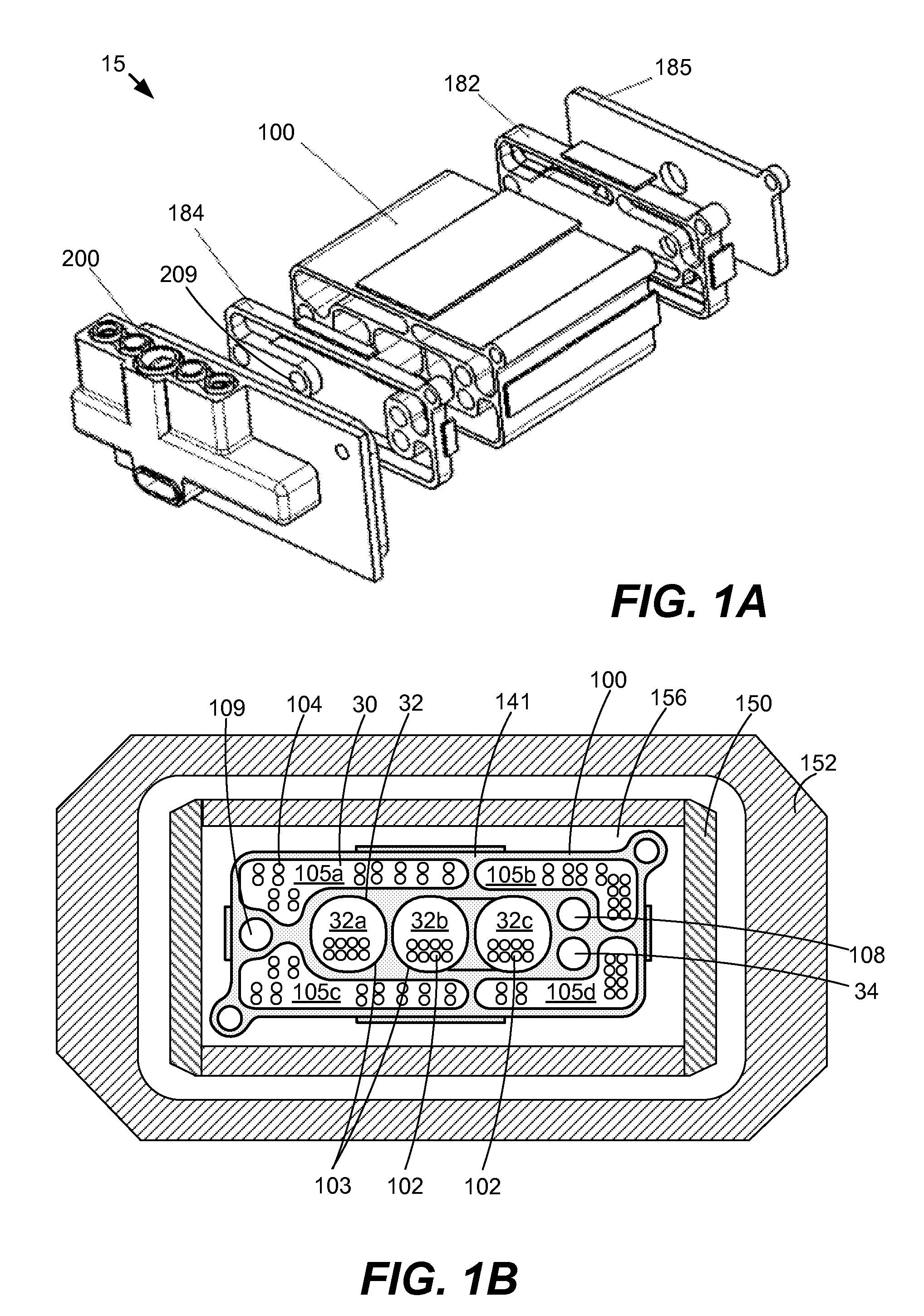
[0022]Embodiments are described herein in the context of a fuel processor for use in a fuel cell system. The following detailed description is illustrative only and is not intended to be in any way limiting. Other embodiments will readily suggest themselves to such skilled persons having the benefit of this disclosure. Reference will now be made in detail to implementations as illustrated in the accompanying drawings. The same reference indicators will be used throughout the drawings and the following detailed description to refer to the same or like parts.

[0023]In the interest of clarity, not all of the routine features of the implementations described herein are shown and described. It will, of course, be appreciated that in the development of any such actual implementation, numerous implementation-specific decisions must be made in order to achieve the developer's specific goals, such as compliance with application- and business-related constraints, and that these specific goals ...


PUM

PropertyMeasurementUnit
diametersaaaaaaaaaa
diametersaaaaaaaaaa
pressureaaaaaaaaaa

Abstract

A method for manufacturing a fuel processor may comprise coupling a plurality of micro-tubes in parallel to form a flow field tube array, each of the plurality of micro-tubes designed to receive a fluid flow, depositing a catalyst layer inside each of the plurality of micro-tubes, and attaching at least one burner to a first end of the flow field tube array.

Description

CROSS REFERENCE TO RELATED APPLICATIONS[0001]This application is a Divisional Application which claims priority under 35 U.S.C. §120 from co-pending U.S. patent application Ser. No. 11 / 835,747, filed on Aug. 8, 2007 entitled “Fuel Processor For Use In A Fuel Cell System”, which claims priority under 35 U.S.C. §119(e) from U.S. Provisional Patent Application No. 60 / 836,859, filed Aug. 9, 2006 both of which are incorporated by reference herein for all purposes.FIELD OF THE INVENTION[0002]The present disclosure relates generally to fuel cell technology. In particular, the invention relates to a fuel processor, used in a fuel cell system, to convert a fuel source to hydrogen.BACKGROUND OF THE INVENTION[0003]Commonly, a fuel processor is often designed specifically for a given fuel cell stack based on the fuel cell's power performance, size and hydrogen fuel consumption requirements. As such, it can only be integrated with a given cell stack. The fuel processor is also a separate device,...

Claims


Application Information

Patent Timeline
Patent Type & Authority Applications(United States)
IPC IPC(8): B21D51/16H01M8/00
CPCB01J8/0449Y10T29/49345B01J8/0492B01J8/0496B01J8/06B01J8/065B01J8/067B01J19/0093B01J19/2495B01J2208/00309B01J2208/00504B01J2208/0053B01J2208/00672B01J2219/00788B01J2219/00835B01J2219/00846B01J2219/0086B01J2219/00869B01J2219/00873B01J2219/00891C01B3/323C01B2203/0233C01B2203/066C01B2203/0811C01B2203/0822C01B2203/0827C01B2203/1017C01B2203/1023C01B2203/1029C01B2203/1064C01B2203/1076C01B2203/1223C01B2203/1288C01B2203/1614H01M8/04022H01M8/0631Y02E60/50B01J8/0484Y02P20/10Y02P70/50
Inventor BRANTLEY, JENNIFERNEWELL, KENNETHSOPCHAK, DAVIDKAYE, IAN W.THOMPSON, JESSESOMOGYVARI, ARPAD
Owner ULTRACELL ACQUISITION
Learn More