
Laser Range Finder

Inactive Publication Date: 2008-11-20
SLIPCHENKO NIKOLAI N
View PDF1 Cites 9 Cited by
  • Summary
  • Abstract
  • Description
  • Claims
  • Application Information

AI Technical Summary

Problems solved by technology

Disadvantages of such laser rangefinder include inability to discriminate object by distance or field of view; e.g., of the field of view contains several objects, or a specular object, or a continuous object, it is not possible to select an object by its angular or reflective characteristics.

Method used


Image

  • Laser Range Finder
  • Laser Range Finder
  • Laser Range Finder

Examples


Embodiment Construction

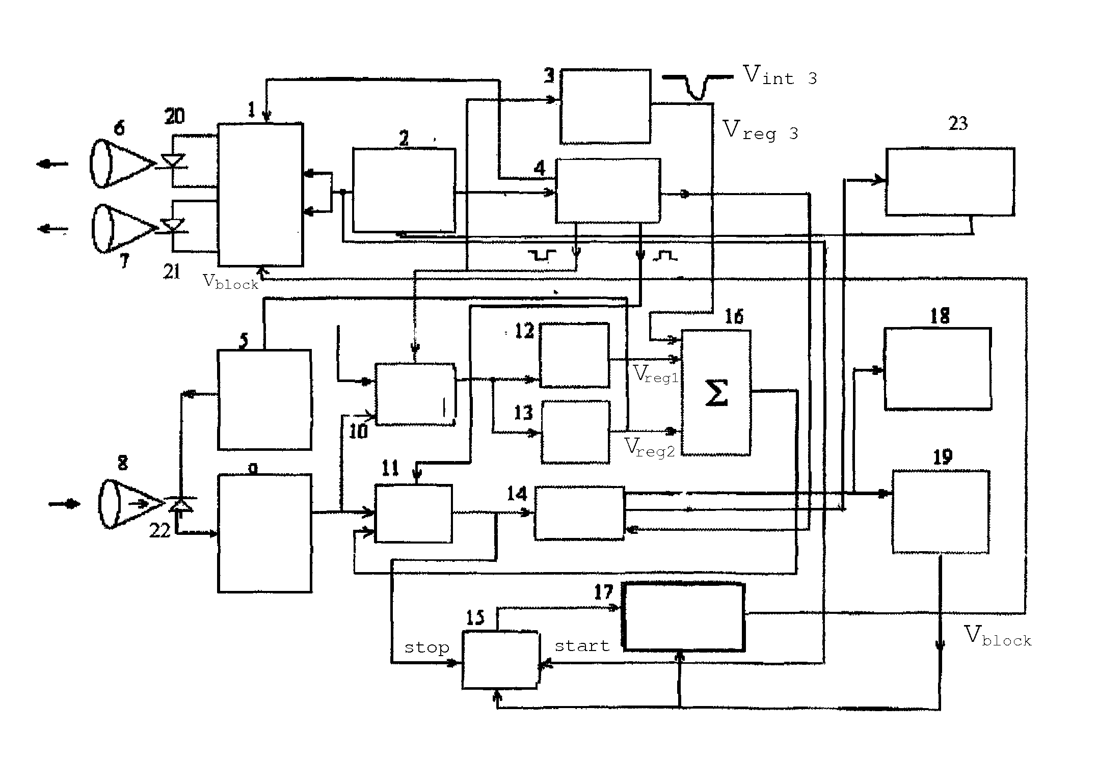
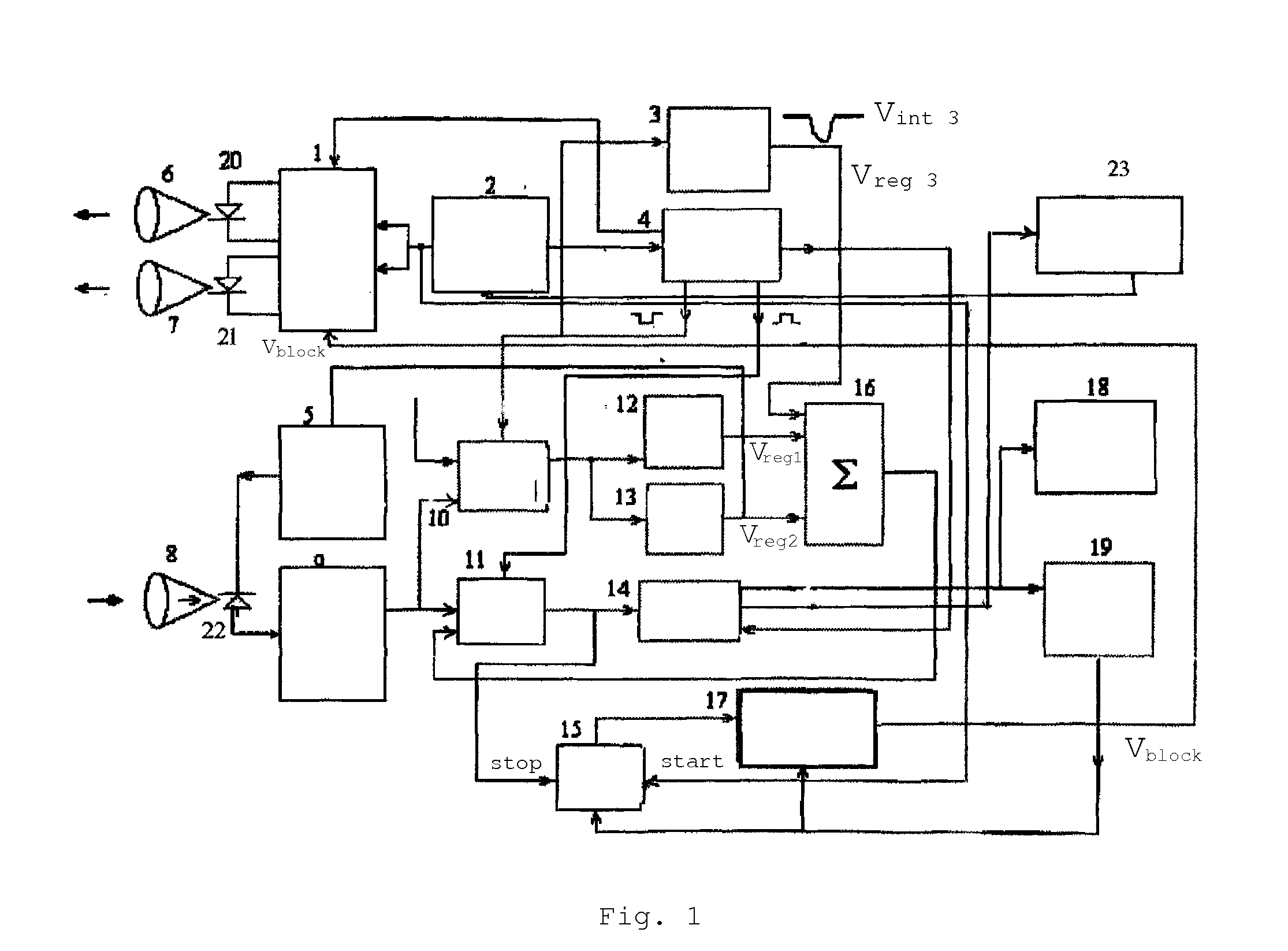
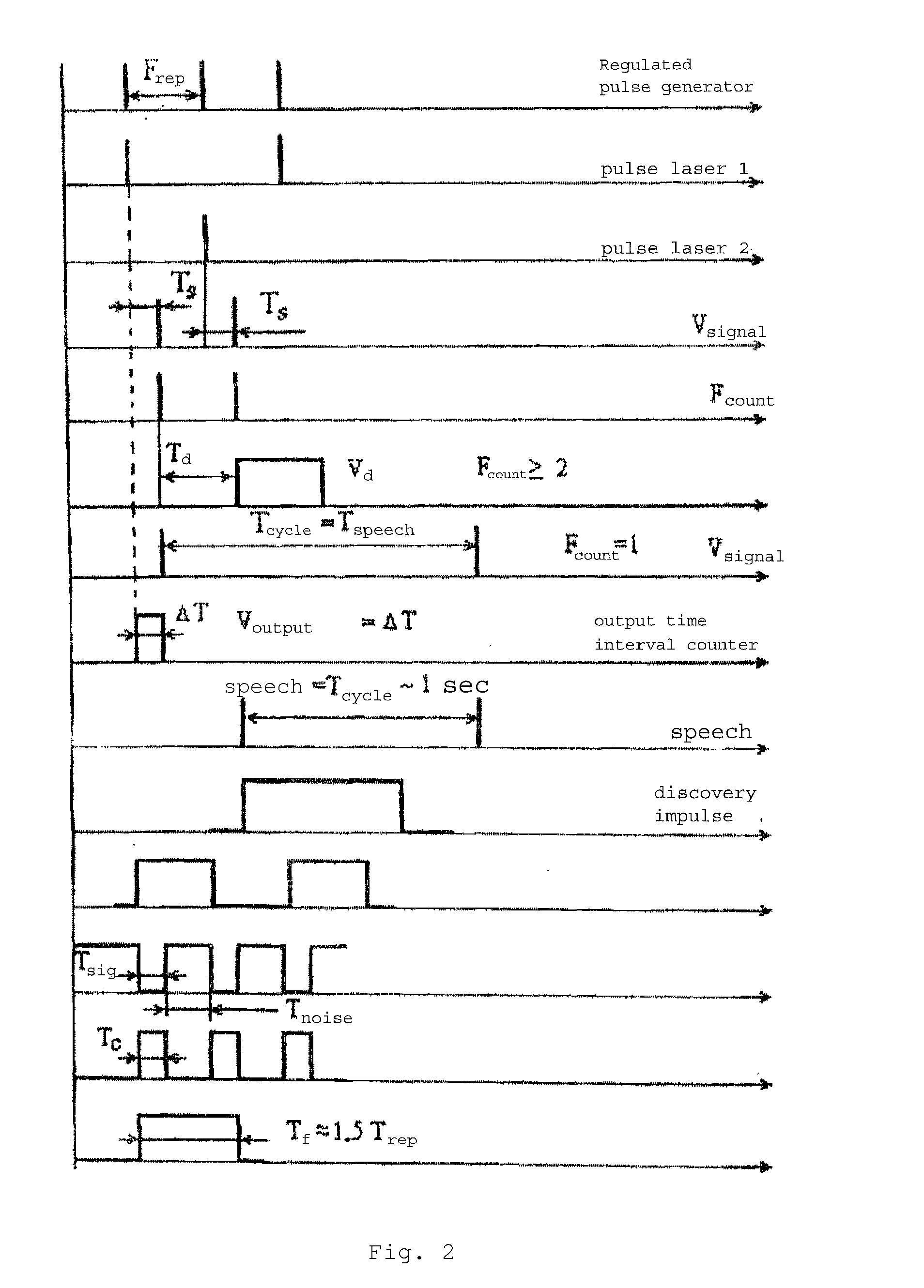
[0027]The dual-channel commutated pulse amplifier (1) has four inputs, two of which (strobe and base) are connected to one of four synchronizer (4) outputs and to the speech synthesizer (17) output, respectively. The remaining two inputs, together with one of the three time-interval meter (15) outputs, are connected to one of the two outputs of the regulated pulse generator (2). The first (20) and second (21) pulse lasers are connected to two outputs of the pulse amplifier (1). The second output of the of the regulated pulse generator (2) if connected to the synchronizer (4) input. Input of the regulated pulse generator (2) is connected to the output of the strobe generator (23); the input of the strobe generator (23) is connected to one of two outputs of the regulated counter (14). Second synchronizer (4) output is connected to one of three inputs (strobe input) of the second comparator (10) and concurrently to the input of the third integrator (3). Third synchronizer (4) output is...


PUM


Abstract

This invention belongs to instruments for distance measurement (rangefinders). The proposed laser rangefinder contains, serially connected, pulse laser with an optical system, a pulse amplifier and a regulated pulse generator; also, serially connected, a photoreceiver based on an avalanche photodiode with an optical system (conjugate to that of the laser), an amplifier of photo-detected signals, comparator, time-interval meter, and an object detection indicator. This rangefinder is unique in that the pulse amplifier features an additional output, connected to which is a second laser with an optical system (conjugate to that of the first laser and avalanche photodiode); and an additional second input connected to the first input of the pulse amplifier, to the first output of the regulated pulse generator and to the first input of the time-interval meter.

Description

RELATED APPLICATIONS[0001]This application claims priority to Russian Patent Application No. RU 2006139526 filed on Nov. 9, 2006, which is incorporated herein by reference in its entirety.BACKGROUND OF THE INVENTION[0002]This invention relates to instruments for distance measurement, such as rangefinders.[0003]Presently, an array of laser rangefinders of different applications is known. An example of one such rangefinder is described in “Systems for optical detection and ranging” by V. V. Molebny (Mashinostroenie, Moscow, 1981, p. 52); and is used to determine distance to an object with range discrimination. It utilizes a pulse laser with an optical collimation system emitting short optical pulses toward the object; exiting start reference pulse is diverted toward a photoreceiver with pulse amplification, which is connected to a start pulse of the time interval counter. The altered time interval, in either analog or digital form, reflects measured distance to the object.[0004]Disadv...

Claims


Application Information

Patent Timeline
IPC IPC(8): G01C3/08
CPCG01S17/10G01S7/4815G01S7/4861G01S7/4873
Inventor SLIPCHENKO, NIKOLAI N.KRYMSKY, MIKHAIL I.
Owner SLIPCHENKO NIKOLAI N
Learn More