Image pickup apparatus and method of correcting captured image data
- Summary
- Abstract
- Description
- Claims
- Application Information
AI Technical Summary
Benefits of technology
Problems solved by technology
Method used
Image

Examples
first embodiment
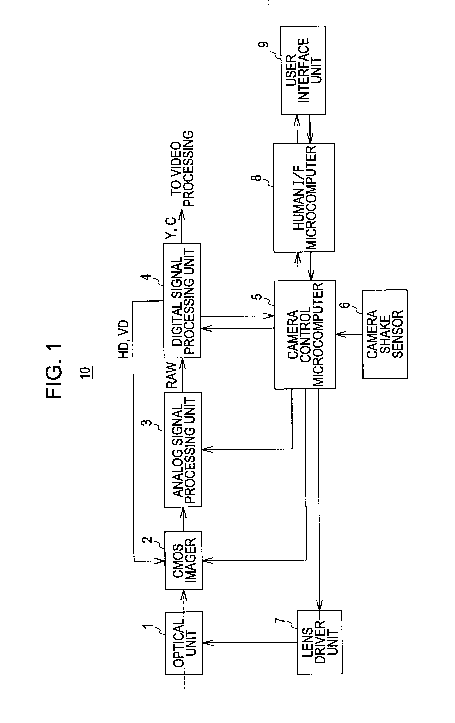
[0044]FIG. 1 is a block diagram showing an example of the configuration of an image pickup apparatus 10 according to a first embodiment of the present invention. The image pickup apparatus 10 includes an optical unit 1 including a lens, a CMOS imager 2 by which a solid-state image pickup device is exemplified, an analog signal processing unit 3, a digital signal processing unit 4, a camera control microcomputer 5, a camera shake sensor 6, a lens driver unit 7, a human interface microcomputer 8, and a user interface unit 9.
[0045]The optical unit 1 is provided with an actuator that adjusts the position of the lens in order to correct camera shaking. The actuator is driven and controlled by a lens drive signal supplied from the lens driver unit 7.
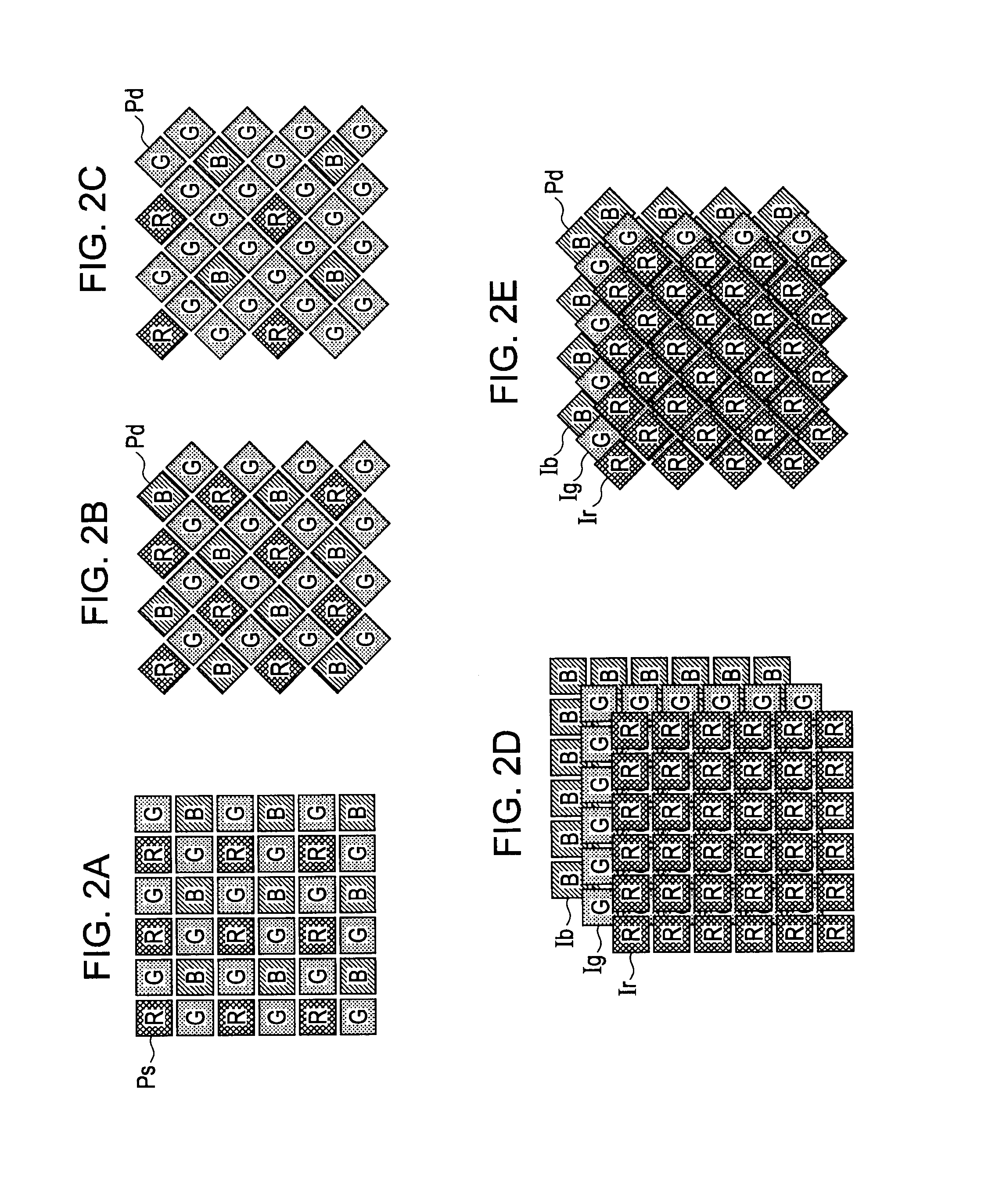
[0046]The CMOS imager 2 has many pixels horizontally and vertically arranged therein. The pixel sharing technology is applied to the CMOS imager 2. The CMOS imager 2 also has color filters arranged at the side on which light is incident in ord...
second embodiment
[0120]Although the detection and correction of the black level is performed for every row in the first embodiment of the present invention, it is preferred that the average black level be calculated by using many pixels in order to increase the effect of the averaging if a vertical variation in the black level with respect to each sharing pixel does not occur because of the characteristics of the solid-state image pickup device.
[0121]Accordingly, according to a second embodiment of the present invention, the sharing-pixel black-level detecting part 41 outputs the sharing pixel black level information BLc for every screen, instead of outputting the sharing pixel black level information BLc for every row.
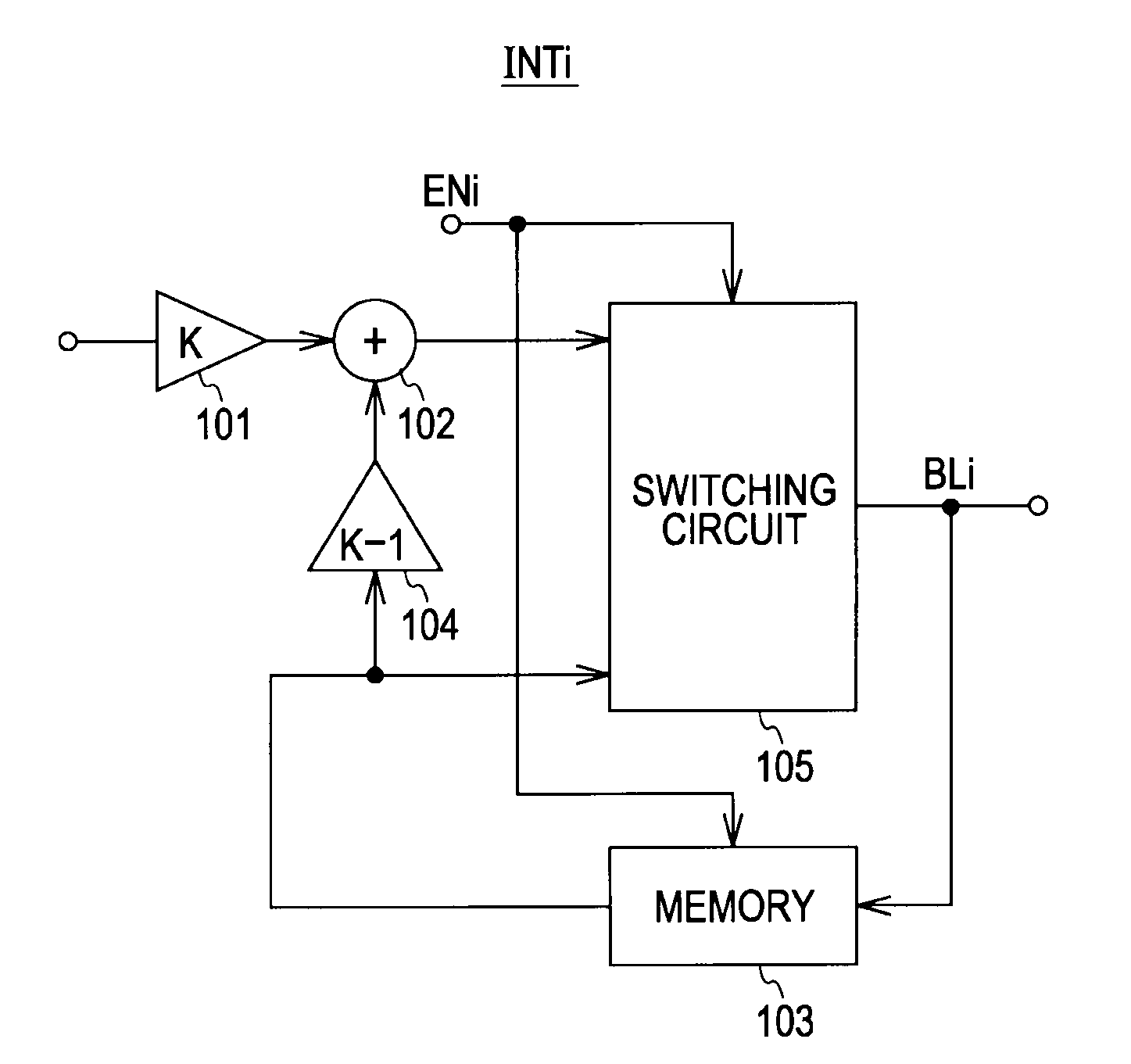
[0122]FIG. 10 is a block diagram showing an example of the configuration of each of the integrators INT1 to INTn in the integrator circuit 4142 in the sharing-pixel black-level detecting part 41 according to the second embodiment of the present invention.
[0123]The integrator INTi show...
third embodiment
[0128]The nonuniformity in the black level between the pixels having different sharing pixel IDs is detected and corrected as the nonuniformity in the pixel characteristics of the sharing pixels in the first and second embodiments of the present invention described above. However, the nonuniformity in the pixel characteristics between the pixels having different sharing pixel IDs is not limited to the nonuniformity in the black level.
[0129]For example, the pixels having different sharing pixel IDs can have different characteristics in terms of the “sensitivity” of the pixels or the “linearity” of the pixel outputs because the direction of the openings of the photodiodes of the pixels differs between the pixels having different sharing pixel IDs. A third embodiment of the present invention is provided in order to resolve such a problem.
[0130]FIG. 11 is a block diagram showing an example of the configuration of a digital signal processing unit 4 according to the third embodiment of th...
PUM
 Abstract
Description
Claims
Application Information
 - R&D
- Intellectual Property
- Life Sciences
- Materials
- Tech Scout
- Unparalleled Data Quality
- Higher Quality Content
- 60% Fewer Hallucinations
Browse by: Latest US Patents, China's latest patents, Technical Efficacy Thesaurus, Application Domain, Technology Topic, Popular Technical Reports.
© 2025 PatSnap. All rights reserved.Legal|Privacy policy|Modern Slavery Act Transparency Statement|Sitemap|About US| Contact US: help@patsnap.com