
Switchable Lens

a technology of active lenses and switches, which is applied in the direction of instruments, color television details, electrical devices, etc., can solve the problems of reduced viewing freedom of observers, user visual strain, and artefacts, and achieve low image crosstalk levels, high brightness, and high quality

Active Publication Date: 2008-11-20
AU OPTRONICS CORP
View PDF8 Cites 64 Cited by
  • Summary
  • Abstract
  • Description
  • Claims
  • Application Information

AI Technical Summary

Benefits of technology

"The present invention provides a display apparatus that uses a switchable birefringent lens to align the polarization of the output display device with the alignment direction of the lens. This allows for better control of the polarization and reduces the need for additional waveplates, reducing the cost and complexity of the display apparatus. The birefringent material is aligned parallel to the geometrical axis of the cylindrical lenses in one mode and at a predetermined angle in another mode. The lens array also has the advantage of achromatic polarization guiding, which simplifies the manufacturing process and reduces the viewing distance of the display. The alignment direction can be parallel or orthogonal to the output polarization of the display device. The invention also provides a method for aligning the birefringent material in the lens array. Overall, the invention improves the performance and cost-effectiveness of display apparatuses using a switchable birefringent lens."

Problems solved by technology

Several artefacts can occur due to inadequate window performance.
This is a significant 3D image degradation mechanism which can lead to visual strain for the user.
Additionally, poor window quality will lead to a reduction in the viewing freedom of the observer.
Parallax barriers rely on blocking the light from regions of the display and therefore reduce the brightness and device efficiency, generally to approximately 20-40% of the original display brightness.
The viewing freedom of the flat panel displays described above is limited by the window structure of the display.
Such an observer measurement apparatus and mechanical actuation is expensive and complex.
As described above, the use of parallax optics to generate a spatially multiplexed 3D display limits the resolution of each image to at best half of the full display resolution.
Such a display suffers from Fresnel diffraction artefacts in the 3D mode, as well as from unwanted residual scatter in the diffuser's clear state which will increase the display cross-talk.
Therefore, such a display is likely to exhibit higher levels of visual strain.
Such a display has increased cost and complexity due to the use of two LCD elements as well as being of reduced brightness or having increased power consumption.
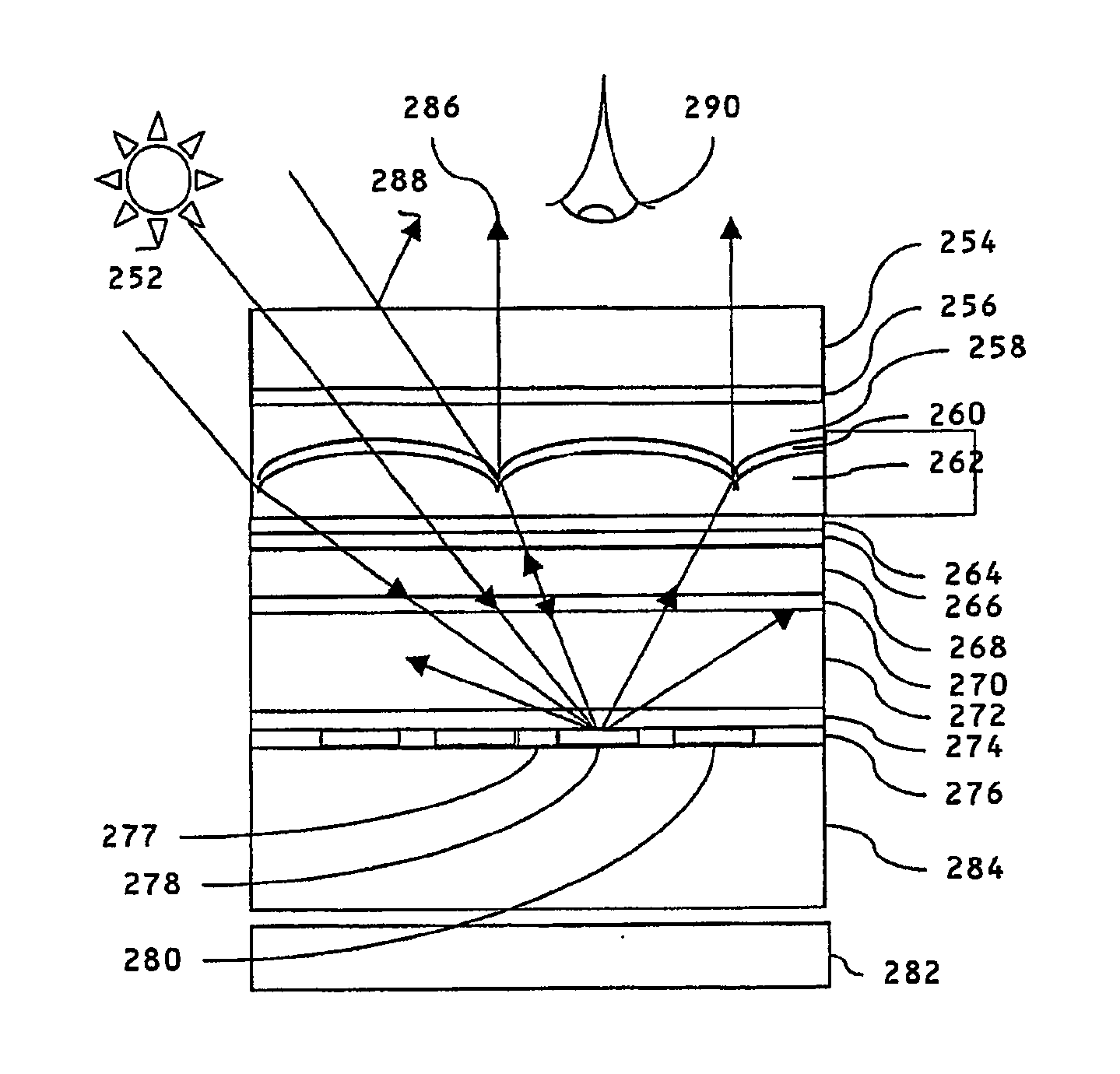
If used in a reflective mode 3D display system, parallax barriers result in very poor brightness due to attenuation of light by the blocking regions of the parallax barrier both on the way in and out of the display.
One disadvantage is that such a display uses parallax barrier technology and thus is limited to perhaps 20-30% brightness in the 3D mode of operation.
Also, the display will have a viewing freedom and cross talk which is limited by the diffraction from the apertures of the barrier.
Therefore the power consumption of the liquid crystal in the driven mode for this kind of lens cell is significantly higher than the power consumption of a standard 5 μm thick LCD using the same liquid crystal and driving frequency.
Therefore it is undesirable to have a 2D driven mode.
Thus a lens array designed to operate at one temperature may have poor optical properties at another temperature.
However, in this range, the voltage controller can reduce the power to adjust the focus of the lens array towards best focus by adjusting the effective refractive index of the birefringent material, so this feature effectively increases the operating temperature range.

Method used


Image

  • Switchable Lens
  • Switchable Lens
  • Switchable Lens

Examples


Embodiment Construction

[0182]Some of the various embodiments employ common elements which, for brevity, will be given common reference numerals and a description thereof will not be repeated. Furthermore the description of the elements of each embodiment applies equally to the identical elements of the other embodiments and the elements having corresponding effects, mutatis mutandis. Also, the figures illustrating the embodiments which are displays show only a portion of display, for clarity. In fact, the construction is repeated over the entire area of the display.

[0183]In this specification, the direction of the optical axis of the birefringent material (the director direction, or the extraordinary axis direction) will be referred to as the birefringent optical axis. This should not be confused with the optical axis of the lenses which is defined in the usual way by geometric optics.

[0184]A cylindrical lens describes a lens in which an edge (which has a radius of curvature and may have other aspheric co...


PUM

PropertyMeasurementUnit
temperaturesaaaaaaaaaa
temperatureaaaaaaaaaa

Abstract

A display apparatus has a switchable birefringent lens array. The display apparatus produces a substantially linearly polarised output. The lens array comprises birefringent material arranged between a planar surface of a first substrate and a relief substrate of a second substrate defining an array of cylindrical lenses. The lens array has electrodes for applying a control voltage across the birefringent material for electrically switching the birefringent material between a first mode and a second mode. In the first mode the lens array modifies the directional distribution of incident light polarised in a predetermined direction. In the second mode the lens array has substantially no effect on incident light polarised in said predetermined direction.

Description

CROSS-REFERENCE TO RELATED APPLICATIONS[0001]This application is a division of U.S. patent application Ser. No. 10 / 544,330, which is a national phase application of PCT / GB04 / 00374, filed Sep. 16, 2005, which PCT application claimed priority to Great Britain application GB 0302658, filed Feb. 5, 2003.BACKGROUND[0002]1. Field of Invention[0003]The present invention relates to optical display apparatus, in particular switchable active lenses for display apparatus. Such a switchable active lens may be used to provide: a switchable two dimensional (2D) / three dimensional (3D) autostereoscopic display apparatus; a switchable high brightness reflective display system; or a multi-user display system. Such display systems may be used in computer monitors, telecommunications handsets, digital cameras, laptop and desktop computers, games apparatuses, automotive and other mobile display applications.[0004]2. Description of Related Art[0005]3D Displays[0006]Normal human vision is stereoscopic, th...

Claims


Application Information

Patent Timeline
Patent Type & Authority Applications(United States)
IPC IPC(8): H04N13/04G02B30/27G02B30/30G02F1/1333G02F1/29H04N13/00
CPCG02B27/2214G02F1/133526G02F1/29G02F2001/294H04N13/0404H04N13/0454H04N13/0456H04N13/305H04N13/359H04N13/361G02B30/27G02F1/294G02B30/30
Inventor WOODGATE, GRAHAM JOHNHARROLD, JONATHAN
Owner AU OPTRONICS CORP
Learn More