
Flexible Pipe, Its Manufacture and Use

a flexible pipe technology, applied in the field of flexible pipes, can solve the problems of inflexible solution, achieve the effects of reducing friction and wear, and facilitating manufacturing and manufacturing

Inactive Publication Date: 2008-11-20
NAT OILWELL VARCO DENMARK
View PDF14 Cites 24 Cited by
  • Summary
  • Abstract
  • Description
  • Claims
  • Application Information

AI Technical Summary

Benefits of technology

[0024]An advantage of the present invention is that in an application yielding a specific inner pressure from the axial armouring and for a specific cord (having a specific elastic modulus and cross sectional area), the radial expansion of the pipe may be controlled (e.g. held below a specific value) by varying the number of cords and the winding pitch. This has the advantage of providing an improved freedom of construction and manufacturing compared to prior art solutions.
[0025]In an embodiment, the innermost armouring layer constitutes or is part of an inner group of layers constituting said radial armouring and providing protection against radial deformations of the flexible pipe originating e.g. from inner and outer operational pressures, outer mechanical actions, etc.
[0026]In an embodiment, the outermost armouring layer constitutes or is part of an outer group of layers constituting said axial armouring and providing protection against axial deformations of the flexible pipe.
[0027]In an embodiment, the winding angle or angles αinner of the armouring layers of the inner group of layers is / are larger than the winding angle or angles αouter of the armouring layers of the outer group of layers. This combination of angles will limit the contact pressures between the layers, thereby reduce friction and wear, thus maximise flexibility and durability of the pipe.
[0028]In an embodiment, the winding angle(s) αinner of the armouring layer(s) of the inner group of layers is / are at least 10° larger than the winding angle(s) αouter of the armouring layer(s) of the outer group of layers, such as at least 20° larger, such as at least 30° larger, such as at least 40° larger, such as at least 50° larger.
[0029]In an embodiment, the winding angle(s) αinner of the armouring layer(s) of the inner group of layers is / are in the range 75° to 90°, preferably around 86°.

Problems solved by technology

This solution is very inflexible with regard to constructional and manufacturing freedom for pipes which are constructed and manufactured for specific applications.
It thus requires inappropriately many variants of these tapes to be able to cost-effectively manufacture flexible pipes in dimensions from 2″ to 16″ (app.

Method used


Image

  • Flexible Pipe, Its Manufacture and Use
  • Flexible Pipe, Its Manufacture and Use
  • Flexible Pipe, Its Manufacture and Use

Examples


Embodiment Construction

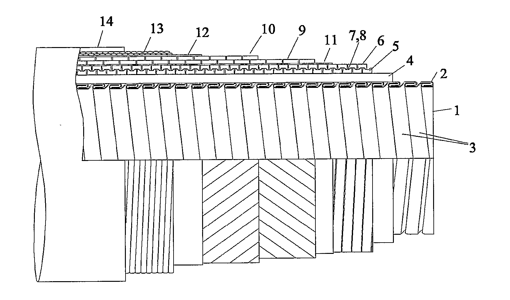
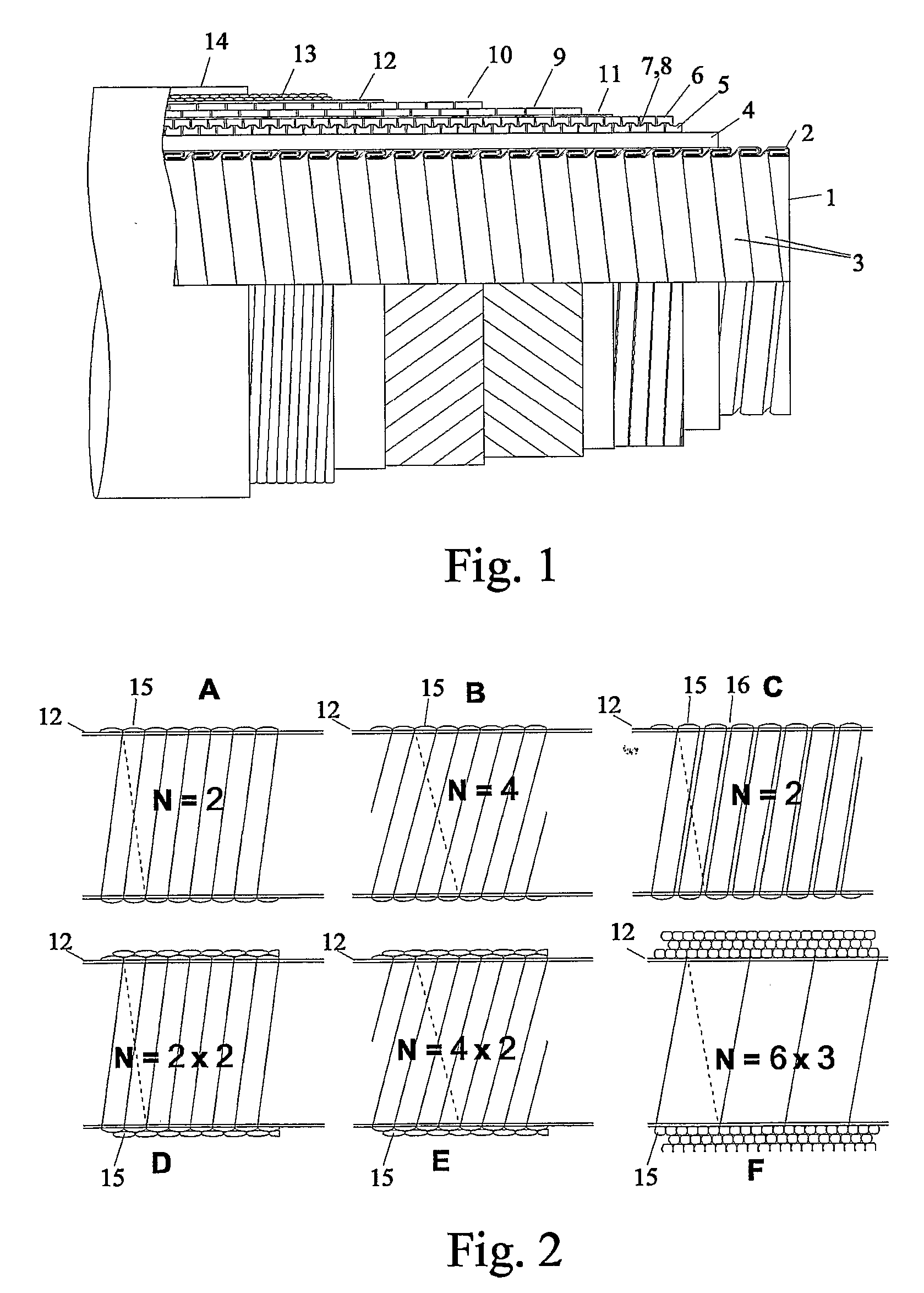
[0074]An embodiment of a flexible pipe according to the invention is shown in FIG. 1. The construction of the pipe is illustrated by the partial cut-out of the pipe.

[0075]The pipe comprises an inner armouring layer 1 (often referred to as an inner carcass) manufactured by winding and folding a metallic tape 2 in such a way that the turns of the tape interlock with each other and thereby limit the displacement between the turns. Around the carcass layer 1, a barrier layer 4 (also termed the inner liner) of a polymeric material has been formed (here by extrusion). Around the barrier layer 4, two armouring layers 5, 6 comprising armouring profiles (here of metallic materials) 7, 8, where the profile 7 of the innermost 5 of the two armouring layers matches the profile 8 of the outermost 6 of the two armouring layers. These two armouring layers 5, 6 have a relatively large winding angle relative to a centre axis of the pipe (here of more than 80°). Around these armouring layers 5, 6 two ...


PUM

PropertyMeasurementUnit
Pressureaaaaaaaaaa
Angleaaaaaaaaaa
Angleaaaaaaaaaa

Abstract

A flexible, typically un-bonded, armoured pipe, and a method manufacturing a flexible pipe. The pipe has a center axis and comprises an inner liner surrounded by a radial armouring and an axial armouring, the radial and axial armouring each comprising at least one armouring layer of armouring profiles wound with winding angles αi relative to the center axis. The winding angle of the innermost armouring layer αinnermost is larger than the winding angle of the outermost armouring layer αinnermost. The outer radial armouring layer has sufficient strength and flexibility to prevent prohibitively large radial deformations of underlying axial armouring layers without considerably increasing the radial contact pressure on underlying axial armouring layer. At least one fibrous layer, comprising at least two fibrous cords wound on an underlying layer, surrounds the outermost armouring layer. The flexible pipe is useful in terrestrial and / or subsea transport of fluids at elevated temperature and / or pressures.

Description

TECHNICAL FIELD[0001]The present invention relates to a flexible pipe comprising an inner liner surrounded by at least two armouring layers and to the control of axial compression induced by radial deformations of underlying axial armouring layers.[0002]The invention furthermore relates to a method of manufacturing a flexible pipe and to its use.[0003]The invention may e.g. be useful in applications such as the transport of fluids at elevated temperatures and or pressures.BACKGROUND ART[0004]The following account of the prior art relates to one of the areas of application of the present invention, flexible pipes for marine applications such as the transport of oil or gas or other fluids in a sub-sea environment.[0005]Such a flexible pipe may e.g. comprise an inner liner forming a barrier against outflow of the fluid being transported in the pipe. The inner liner may typically be surrounded by one or more layers of one or more wound armouring profiles. The armouring layers may—depend...

Claims


Application Information

Patent Timeline
IPC IPC(8): F16L11/02F16L11/00B23P19/00F16L11/08F16L11/16
CPCF16L11/083Y10T29/49881B29C53/58F16L11/16
Inventor RYTTER, JAN
Owner NAT OILWELL VARCO DENMARK
Learn More