Moving picture decoding integrated circuit

a picture and integrated circuit technology, applied in the direction of color television with bandwidth reduction, signal generator with optical-mechanical scanning, signal system, etc., can solve the problems of unrealistic handling of such a huge amount of information in a digital format, power consumption will become large, and it is impossible to send an image taken by a tv camera via isdn, etc., to achieve excessively increasing the capacity of cache memory, reducing the transfer bandwidth, and maximizing the reduction of transfer bandwidth

Inactive Publication Date: 2008-11-13
PANASONIC CORP
View PDF4 Cites 31 Cited by
  • Summary
  • Abstract
  • Description
  • Claims
  • Application Information

AI Technical Summary

Benefits of technology

[0034]An object of the present invention is providing a moving picture decoding device capable of reducing the transfer bandwidth for pixel data to / from a multi-frame memory while limiting the capacity of a cache memory mounted therein to a small value.

Problems solved by technology

It is therefore unrealistic to handle such a huge amount of information in a digital format as it is in the above information media.
While videophones, for example, have already been put into practical use via an integrated services digital network (ISDN) having a transmission speed of 64 Kits / s to 1.5 Mbits / s, it is impossible to send an image taken by a TV camera via ISDN as it is.
In this case, therefore, as in the coding processing described above, the multi-frame memory FrmMem will need to be constructed of a high-speed SRAM, and the power consumption will become large.
In particular, for a camcorder **and the like for taking a moving picture, which are battery-driven in many cases, increase in power consumption poses a serious problem.
In moving picture coding, therefore, the number of pictures referred to can be reduced depending on the coding performance required, and thus a limitation can be imposed on the capacity of the cache memory.
It is therefore difficult to freely impose a limitation on the capacity of the cache memory.
It is therefore difficult to reduce the capacity to an arbitrary small value.
As a result, in a moving picture decoding device, the capacity of the cache memory must be set to be larger than that of the cache memory mounted in a moving picture coding device, and this causes a problem of cost increase.

Method used


Image

  • Moving picture decoding integrated circuit
  • Moving picture decoding integrated circuit
  • Moving picture decoding integrated circuit

Examples


embodiment 1

[0070]Embodiment 1 will be described with reference to FIGS. 1 to 6.

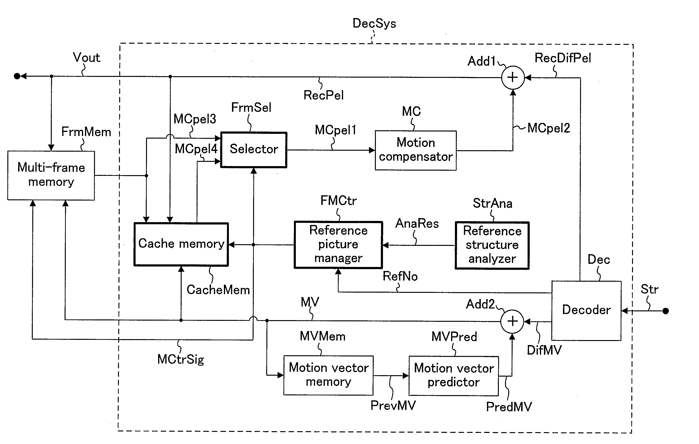
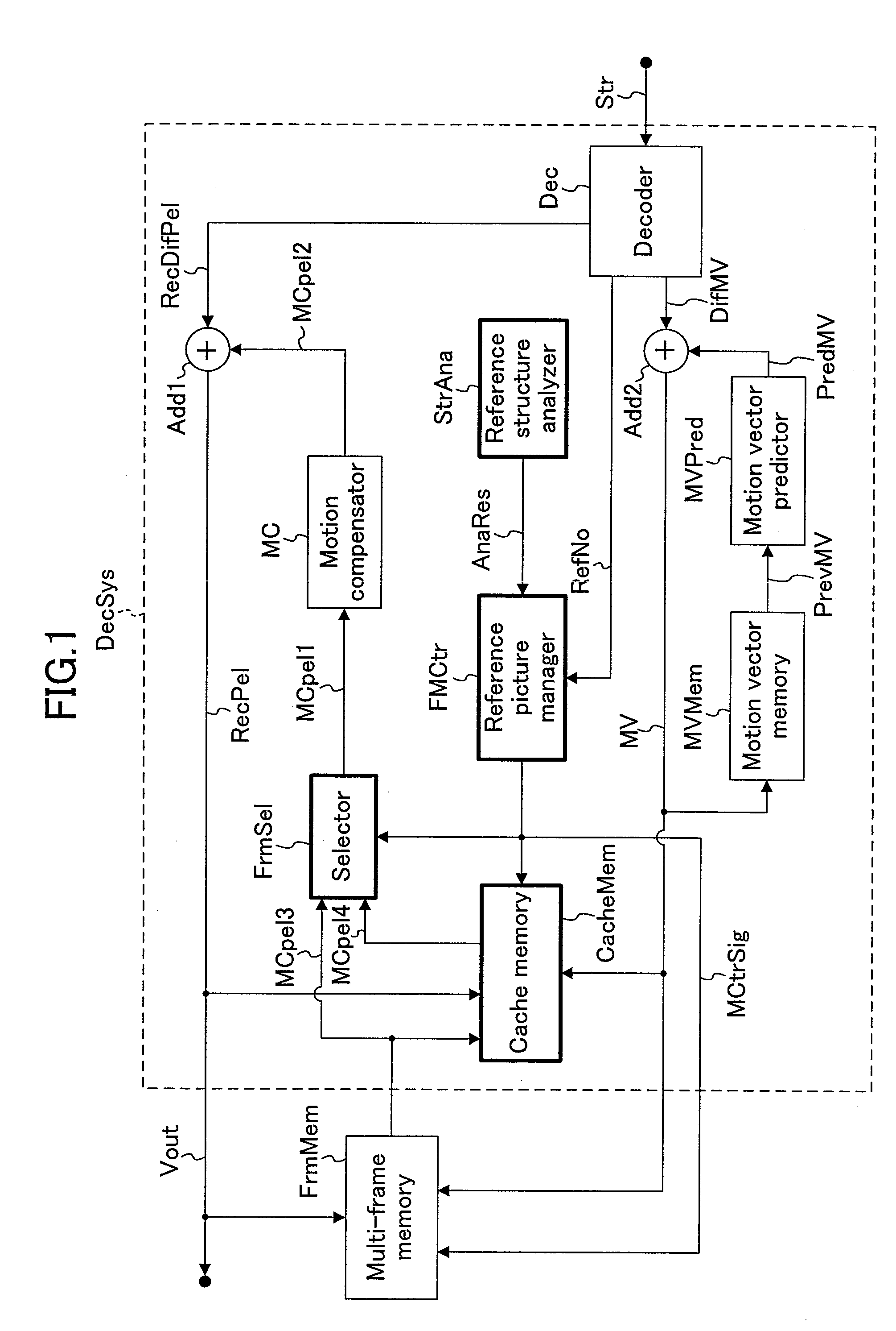
[0071]FIG. 1 is a block diagram of a decoding device for implementing the present invention. In FIG. 1, the same symbols as those in FIG. 10 denote the same components and signals, and the description thereof is omitted here. The configuration of FIG. 1 is different from that of FIG. 10 in that a cache memory CacheMem is provided in addition to a multi-frame memory FrmMem for storing pictures and that a selector (selection circuit) FrmSel, a reference picture manager (reference picture management circuit) FMCtr and a reference structure analyzer (reference structure analysis circuit) StrAna are additionally provided.

[0072]A flow of processing in the configuration including the cache memory CacheMem, the selector FrmSel, the reference picture manager FMCtr and the reference structure analyzer StrAna will be described. First, the reference structure analyzer StrAna analyzes the structure of a stream that is being deco...

embodiment 2

[0108]Embodiment 2 of the present invention will be described with reference to FIG. 6. In this embodiment, the memory management method is changed in special playback because use of the normal management of the cache memory CacheMem may cause redundant memory input / output control.

[0109]FIGS. 6A to 6C are third set of diagrammatic views showing reference pictures managed according to the present invention. In FIGS. 6A to 6C, P0 P600, P1 P601, P4 P604, P7 P607, B2 B602, B3 B603, B5 B605, B6 B606, B8 B608 and B9 B609 respectively correspond to P0 P400, P1 P401, P4 P404, P7 P407, B2 B402, B3 B403, B5 B405, B6 B406, B8 B408 and B9 B409. Also, cm6 P1, cm6P4 and cm6P7 represent the memory management states of P pictures existing next to P1 P601, P4 P604 and P7 P607, respectively.

[0110]Multiple-speed playback is one type of special playback. Referring to FIGS. 6A to 6C, a method for simple multiple-speed playback will be described briefly. FIG. 6A shows pictures lined in order of display d...

embodiment 3

[0114]Embodiment 3 of the present invention will be described. In this embodiment, an image coding / decoding device in which the moving picture decoding device described above is combined with a moving picture coding device will be described as an application of the moving picture decoding device.

[0115]FIG. 7 is a block diagram of an AV processor for implementing an H.264 recorder. In FIG. 7, exAVLSI denotes an AV processing part of a DVD recorder, a hard disk recorder and the like for playing back digital-compressed sound / images.

[0116]In FIG. 7, also, exStr denotes sound / image stream data, and exVsig and exAsig respectively denote image data and sound data. A bus exBus transfers data such as the stream data and decoded data of sound and images. A stream input / output (I / O) section exStrIF for receiving the stream data exStr is connected to the bus exBus at one terminal and to a large-capacity storage device at the other terminal. An image coding / decoding section exVCodec codes / decode...


PUM


Abstract

A moving picture decoding device includes a cache memory for storing a reference picture, in addition to a multi-frame memory (external memory) for storing reference pixel data of a plurality of reference pictures, for processing of a HD image size large in angle of view. A reference structure analyzer analyzes the reference structure of pictures. A reference picture manager not only writes a reference picture high in the possibility of being referred to by an object picture to be decoded in the multi-frame memory but also stores such a reference picture in the cache memory, using the analysis results of the picture reference structure. This minimizes the capacity of the cache memory and also reduces the data transfer amount from the external memory.

Description

CROSS-REFERENCE TO RELATED APPLICATIONS[0001]This non-provisional application claims priority under 35 U.S.C. §119(a) on Patent Application No. 2007-122623 filed in Japan on May 7, 2007, the entire contents of which are hereby incorporated by reference.BACKGROUND OF THE INVENTION[0002]The present invention relates to a moving picture decoding device that reduces the bus bandwidth to / from an image data storage memory in playback of a moving picture stream.[0003]In recent years, with the advent of the multimedia age in which pixel values of sound, images and the like are handled in an integrated manner, the conventional information media, that is, the means for conveying information to people such as newspapers, magazines, TVs, radios and phones have increasingly become taken up as subjects of multimedia. In general, the multimedia refers to simultaneous expression of, not only characters, but also graphics, sound, and especially images, for example, in association with one another. I...

Claims


Application Information

Patent Timeline
IPC IPC(8): H04N7/26H04N19/50H04N19/102H04N19/134H04N19/172H04N19/196H04N19/42H04N19/423H04N19/426H04N19/44H04N19/503H04N19/51H04N19/577
CPCH04N19/61H04N19/433H04N19/44
Inventor IGUCHI, MASAYASUTAKAHASHI, JUN
Owner PANASONIC CORP
Why Eureka
Try Eureka