Optical limiter

a technology of optical limiters and power limiters, which is applied in the direction of optical elements, lighting and heating apparatuses, instruments, etc., can solve the problems of large volume of liquid to be heated, large amount of energy propagation, and high power requirements

Active Publication Date: 2008-11-13
ELBIT SYST LTD
View PDF52 Cites 11 Cited by
  • Summary
  • Abstract
  • Description
  • Claims
  • Application Information

AI Technical Summary

Benefits of technology

[0016]The optical power-limiting device can offer the following advantages and properties:

Problems solved by technology

Another problem is laser safety, wherein there are well-defined upper power limits allowed to be emitted from fibers into the open air.
These two issues call for a passive device that will limit the amount of energy propagating in a fiber / waveguide to the allowed level.
Both No. 1 and 2 of the above-mentioned techniques require very energetic laser beams or light intensities to produce a meaningful limitation.
In the first technique, the volumes of liquid to be heated are large and need high powers.
Another problem with this method is that the liquid is not a good optical medium and distorts the beam.
In the second technique, the n2 coefficient is very small for usable materials and requires very high electric fields.
In the third method, the use of liquids is problematic for most applications.
In a communications system, for instance, the use of liquids in a passive device causes noise and distortion from turbulence of the liquid in the optical path.
Other problems reported using the colloidal liquid as an optical-limiting medium include aging either by disappearance of the active carbon material or the formation of flocs of loosely bound carbon particles that break up only after ultrasonic deflocculation.
Some work has been done on using liquid crystals as limiting material, mainly for high power pulses but these materials cause noise and distortion worse than ordinary liquids due to director fluctuations.

Method used


Image

  • Optical limiter
  • Optical limiter
  • Optical limiter

Examples


Embodiment Construction

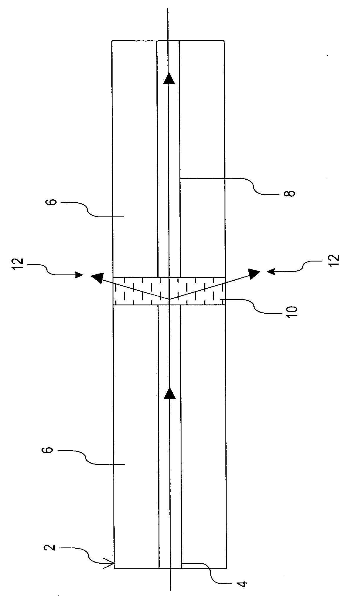
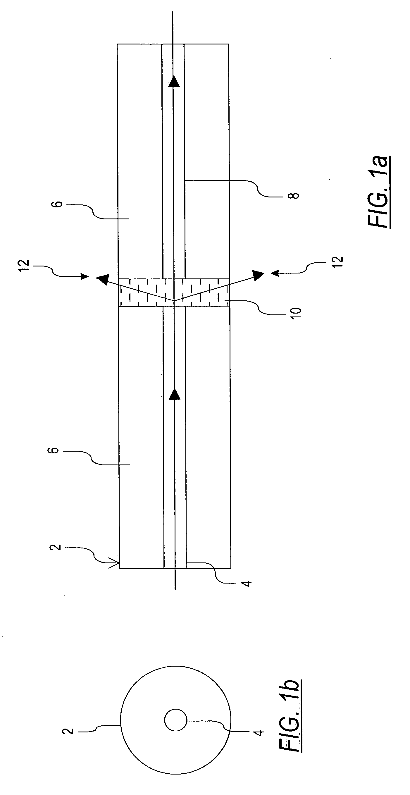
[0050]In the limiter configuration and operation illustrated in FIGS. 1a and 1b, light enters a fiber or waveguide 2 having a core 4 and a cladding 6 (e.g., SMF 28 by Corning, USA), and impinges on an optical-limiting solid mixture 10 placed at the exit of the core 4. The optical-limiting solid mixture 10 is composed of a suspension of light absorbing particles, smaller than the wavelength of visible light (smaller than 0.5 microns) and preferably smaller than 0.1 microns (nano-powder) equally distributed or suspended in a solid, e.g., polymer, material having a large negative index change with temperature (dn / dT). The absorbing material include at least one metallic or non-metallic material selected from the group consisting of: Ag, Au, Ni, Va, Ti, Co, Cr, C, Re, Si and mixtures of such materials. The polymer host material, having a large (dn / dT), may be: PMMA or its derivatives, polymer based on epoxy resins, glass, spin-on glass (SOG) or other sol-gel materials. The optical-limit...


PUM

PropertyMeasurementUnit
diameteraaaaaaaaaa
wavelengthaaaaaaaaaa

Abstract

An optical power limiter comprises an input optical transmission element, an output optical transmission element, and a power-limiting element disposed between the input and output elements for transmitting optical signals from the input element to the output element. The power-limiting element comprises an optical-limiting solid mixture containing particles of at least one material that produces reversible thermal changes in response to light above a predetermined optical power level, thereby changing the optical transmission properties of the power-limiting element.

Description

CROSS-REFERENCE TO RELATED APPLICATION[0001]This application is a Continuation-In-Part of PCT Application No. PCT / IL 03 / 00017 filed Jan. 6, 2003, which claims priority from Israel Patent Application No. 147554 filed on Jan. 10, 2002.FIELD OF THE INVENTION[0002]The present invention relates to optical power-limiting device, and more particularly, to an optical power-limiting passive device and to a method for limiting optical power transmission.BACKGROUND OF THE INVENTION[0003]Optical limiters are devices designed to have high transmittance for low level light inputs and low transmittance for high power. Since the development of the first lasers, passive optical limiters have been researched and concepts have been tested to protect optical sensors against laser peak-power induced damage. The first optical limiters for CW lasers were based on thermal lensing in absorbing bulk liquids, i.e., local heating in an imaging system reduced the index of refraction, causing “thermal blooming” ...

Claims


Application Information

Patent Timeline
Patent Type & Authority Applications(United States)
IPC IPC(8): H01S3/10G02B6/14G02B6/26G02F1/01
CPCG02B6/14G02B6/266G02F1/011G02F1/0147G02F2203/48
Inventor FARBER, ALLANDONVAL, ARIELANEVO, DORONORON, MOSHEORON, RAM
Owner ELBIT SYST LTD
Why Eureka
Try Eureka