
Composite structure and production method thereof

Active Publication Date: 2008-11-06
TOTO LTD
View PDF20 Cites 8 Cited by
  • Summary
  • Abstract
  • Description
  • Claims
  • Application Information

AI Technical Summary

Benefits of technology

[0013]In turn, in plasma resistant products for vacuum apparatuses in which a plasma resistant film such as an yttrium oxide film is formed by the aerosol deposition method on a base material having a ceramic surface, yttrium oxide is gradually consumed from a surface of the yttrium oxide film due to plasma irradiation. In the case where the film has the above-described drawbacks, such consumption is so violent as to cause corrosion of the base material, thereby raising problems of generation of unnecessary particles and formation of irregularity on the base material.
[0017]forming a structure comprising the brittle material on the base material surface having the surface comprising the ceramics polycrystal having the average surface roughness (Ra) of 100 nm or less by generating an aerosol by mixing a powder comprising particles of the brittle material and having a 50%-average particle diameter on volumetric basis of 0.1 to 1.0 μm with a carrier gas and injecting the aerosol to the base material surface having the surface comprising the ceramic polycrystal at a high speed.
[0022]When the average roughness (Ra) of the interface between the anchor part and the base material surface is 100 nm or less, it is possible to perform film re-formation by exposing the base material surface by removing a residual layer by the method such as dissolution after a certain amount of the plasma resistant film is consumed due to the plasma irradiation. Alternatively, after exposing the base material, the surface is subjected to a simple polishing processing such as buff polishing to obtain easily and in a short time a surface having appropriately small surface roughness (Ra) of the base material that will not cause defects on the film, thereby making it possible to use the regenerated base material for film re-formation (repair). Thus, it is possible to obtain a dense and uniform film again.
[0024]The average roughness (Ra) of an interface between the anchor part and the base material surface may preferably be 10 nm or more. The average roughness of 10 nm or more improves an adhesion property. That is, the average roughness (Ra) of the interface between the anchor part and the base material surface may preferably be in the range of 10 to 100 nm, more preferably 10 to 90 nm, particularly preferably 10 to 30 nm.

Problems solved by technology

As is disclosed in Non-patent Reference 1, in the case of adapting the aerosol deposition method to a ceramic base material, it has been difficult to form a film on a mirror surface having surface roughness of 100 nm or less.
Also, though it has been possible to form a film in the case where the base material surface roughness exceeds 100 nm, there have been problems of restricted formation conditions and unable to achieve a dense structure due to influences of minute irregularity and pores existing on the surface.
Also, in the case where relatively large pores exist on the surface, there have been drawbacks that a ceramic film formation is impossible or a film is subject to peeling after the film formation since fine particles that did not form a film are accumulated and clogged inside the pores.
That is, it has been difficult to ensure a uniform and high quality film on a whole surface having a certain film area.
In the case where the film has the above-described drawbacks, such consumption is so violent as to cause corrosion of the base material, thereby raising problems of generation of unnecessary particles and formation of irregularity on the base material.
However, in the case where there is a defect such as a partial lack of the film or deficiency in film density as described above, there has been a problem that it is impossible to perform the repair due to roughening of the surface that is caused by unnecessary corrosion of a part of the base material by the plasma.

Method used


Image

  • Composite structure and production method thereof
  • Composite structure and production method thereof

Examples


example 1

[0061]Yttrium oxide (Y2O3) fine particles and aluminum oxide (Al2O3) fine particles were prepared. 50%-average particle diameters on volumetric basis of the yttrium oxide fine particles and the aluminum oxide fine particles were 0.47 μm and 2.1 μm.

[0062]These fine particles were mixed at a number ratio of 1:10 (aluminum oxide fine particles:yttrium oxide fine particles) to obtain a particle mixture.

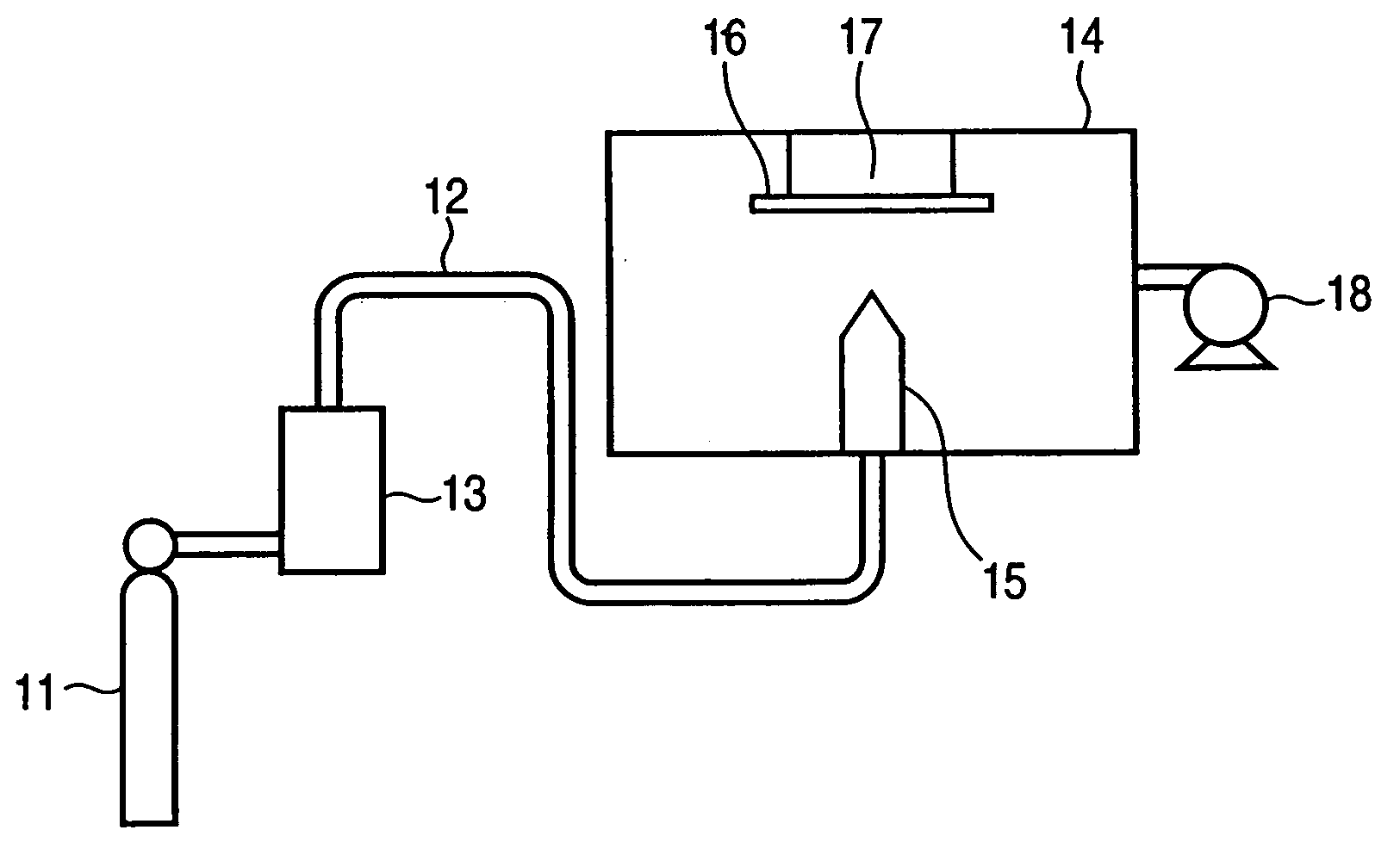
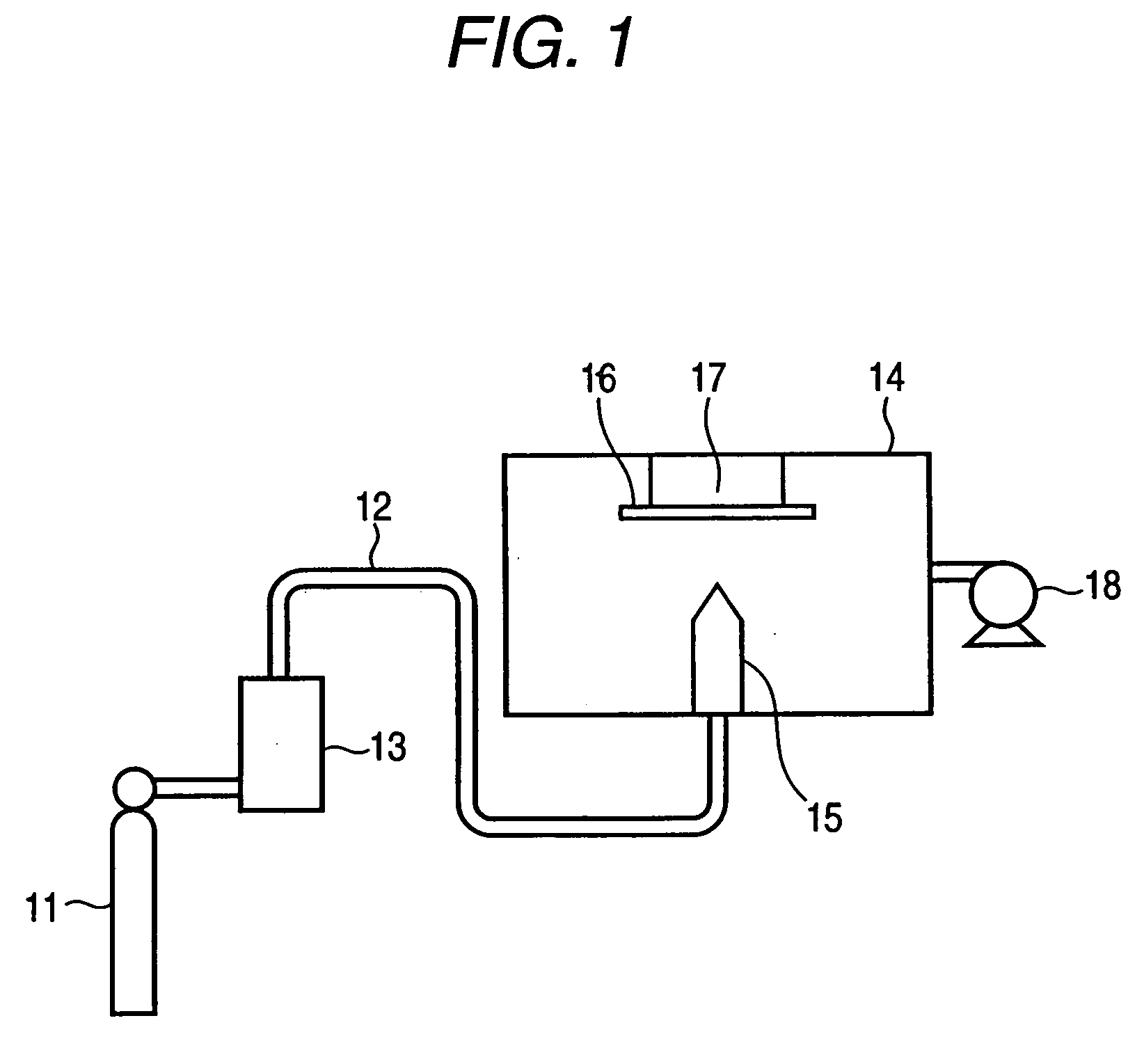
[0063]The particle mixture was charged into an aerosol generator of the apparatus, and an aerosol generated by supplying a nitrogen gas as a carrier gas at a feed rate of 5 L / min was injected to a quartz base material. Thus, an yttrium oxide film having a height of 10 μm, an area of 20 mm×20 mm, and a light transmitting property was formed on the base material.

[0064]A plasma resistance test result and a contact strength measurement result of the thus-obtained yttrium oxide film are shown in Table 1. In the plasma resistance test, plasma processing was performed by using a parallel flat pl...


PUM

PropertyMeasurementUnit
Lengthaaaaaaaaaa
Nanoscale particle sizeaaaaaaaaaa
Surface roughnessaaaaaaaaaa

Abstract

It is intended to provide a composite structure excellent in resistance characteristics such as plasma resistance. The composite structure includes a base material having a surface containing a ceramic polycrystal and a structure formed on the surface of the base material containing the ceramic polycrystal, wherein the structure contains a polycrystal containing a brittle material; a grain boundary layer having a glass layer does not substantially exist on a boundary face between crystals forming the polycrystal; a part of the polycrystal forms an anchor part embedded into the base material surface; and an average roughness (Ra) of an interface between the anchor part and the base material surface is 100 nm or less.

Description

CROSS-REFERENCE TO RELATED APPLICATIONS[0001]This application claims priority from Japanese Patent Application No. 2007-118739 filed on Apr. 27, 2007, the entire subject matter of which is incorporated herein by reference.BACKGROUND OF THE INVENTION[0002]1. Field of the Invention[0003]An embodiment of this invention generally relates to a composite structure in which a structure containing a polycrystal comprising a brittle material is formed on a surface of a base material and a production method thereof.[0004]2. Description of the Related Art[0005]A method called aerosol deposition is disclosed in Patent Reference 1 as a method for forming a structure of a brittle material on a surface of a base material without any heating process and has widely been accepted.[0006]The aerosol deposition method is characterized by injecting from a nozzle to a base material an aerosol obtained by dispersing fine particles of a brittle material or the like into a gas; bonding the brittle material f...

Claims


Application Information

Patent Timeline
IPC IPC(8): C23C16/00B32B5/00
CPCC23C16/4404Y10T428/24355H01J37/32467C23C24/04
Inventor IWASAWA, JUNICHIHATONO, HIRONORI
Owner TOTO LTD
Learn More