Holographic Record Carrier

a record carrier and holographic technology, applied in the field of holographic record carriers, can solve the problems of deteriorating recording characteristics, wasteful use of holographic recording layer performance, and rotator of bisect azimuth, and achieve the effect of recording or reproducing information, recording and reproducing stability

Inactive Publication Date: 2008-11-06
PIONEER CORP
View PDF6 Cites 9 Cited by
  • Summary
  • Abstract
  • Description
  • Claims
  • Application Information

AI Technical Summary

Benefits of technology

[0009]It is therefore an exemplary object of the present invention to provide a holographic record carrier, a recording / reproducing and hologram device capable of providing recording and reproduction stability.
[0010]It is therefore an exemplary object of the present invention to provide a holographic record carrier, a recording / reproducing method therefor, and a hologram apparatus which are capable of stably recording or reproducing information.

Problems solved by technology

However, the conventional method involves a problem that the bisect azimuth rotator and the objective lens must be integrally driven.
The conventional method also has a problem of a deteriorated recording characteristic from reproduced light corresponding to the vicinity of the division boundary of the bisect azimuth rotator.
In the case that a hologram is recorded in such a holographic record carrier of reflective type, four kinds of hologram are recorded by interference due to four light beams of entering reference light and signal light and reflected reference light and signal light, thereby wastefully using holographic recording layer performance.
Further, when reproducing information, it is difficult to separate diffracted light caused by a reproduced hologram from reflected reference light, because the reference light is reflected from the reflective film of the holographic record carrier.
Accordingly, readout performance of the reproduced signal is deteriorated.
Further, since a reflected hologram image is recorded, the reproduced signal is deteriorated.

Method used


Image

  • Holographic Record Carrier
  • Holographic Record Carrier
  • Holographic Record Carrier

Examples


example 1

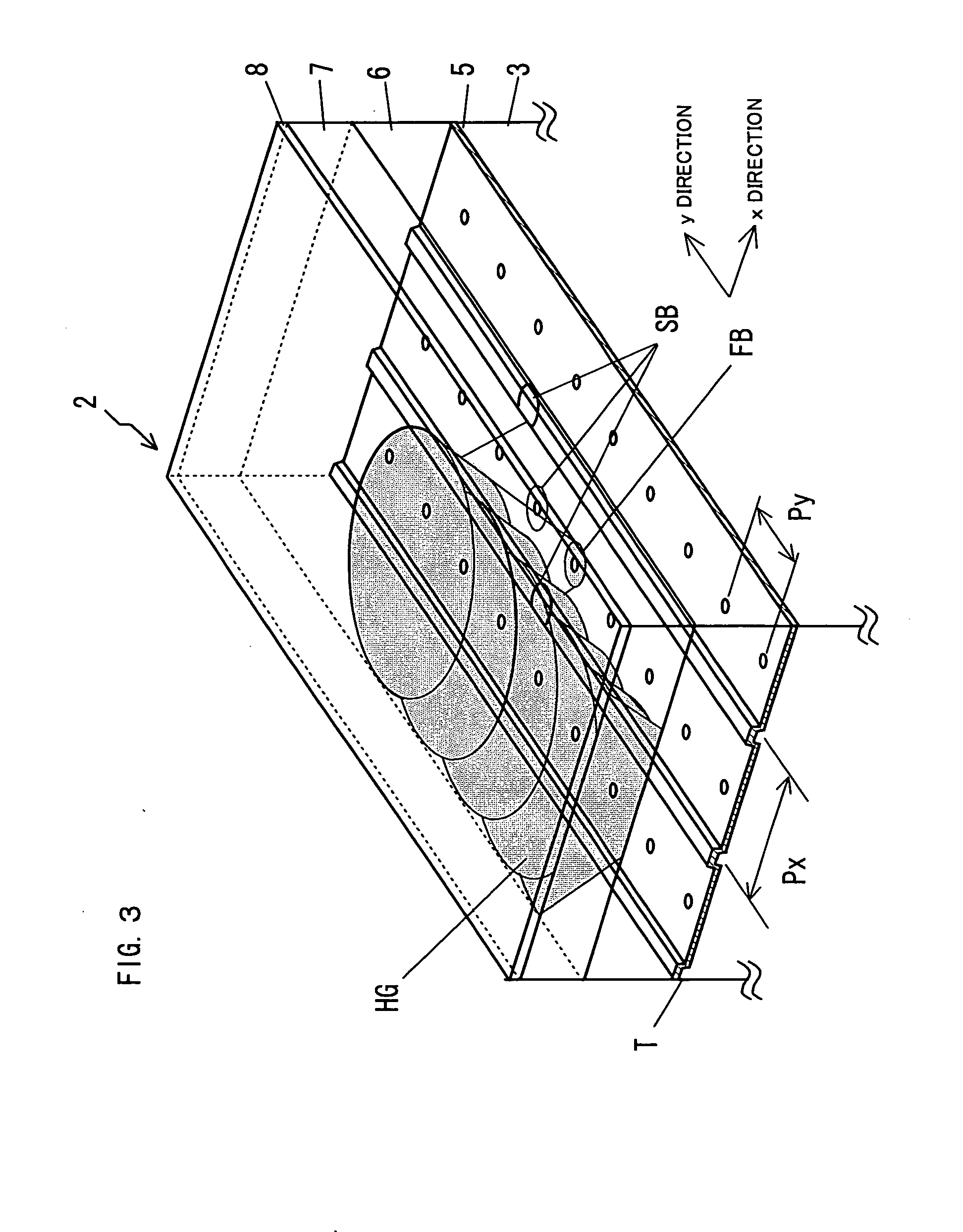
[0085]As shown in FIG. 15, each of pitches Px and Py of the pinhole PH Px of the refractive layer 5 is set as a predetermined distance which is determined by a multiplicity of holograms HG recorded above the spot of the first light beam FB. A maximum multiplicity in an actual shift multiplex recording hologram system (i.e., a value (number of times) indicating how many independent holograms can be recorded within the same volume in a holographic recording medium) is determined by the medium and the configuration of the apparatus, as mentioned above. A minimum pitch Px (i.e., a minimum shift distance) is set by a span of a recorded hologram area divided by the maximum multiplicity. The track pitch Px is set at the minimum shift distance or more.

[0086]A position determination servo control with the holographic record carrier 2 is always performed by using the servo beam SB and at the same time, recording of the hologram is performed using a first light beam FB. The servo control may b...

example 2

[0087]As shown in FIG. 16, in case that the same track T as the holographic recording interval Py is formed between mark arrays of the pinhole PH, while the servo beam SB is set 3 beams by the diffraction optical device such as a grating and the x and y direction servo is performed using 2 side beams, recording is performed using the main beam. That is, a optical axis of the first light beam FB is arranged and tracking servo controlled in order to position the first light beam FB on a straight line or in the center of the light spot of 3 servo beams SB, and the holographic recording is performed in the holographic recording layer 7 of an upper part of a mirror plane part between adjacent tracks.

example 3

[0088]As shown in FIG. 17, a hologram multiple interval Px is set along the x-direction, and a track T extending along the y-direction of the hologram multiple direction and a mask Y identical to the multiple interval Py along the y-direction can be formed in a disk format. The track T of the reflective layer 5 is also the pitch Px, which is set by a predetermined distance determined as a multiplicity of the hologram HG that is recorded in an upper part of the spot of the first light beam FB. As shown in the drawing, when recording the hologram, the servo beam SB is divided into 3 beams by the grating. In order that the main beam in the center of the servo beam is arranged between the tracks T, the side beam is arranged on the track T. Tracking servo control is performed where the objective lens OB follows the track T using the push / pull method from the detection signal of the side beam. The spot of the first light beam is matched with the pinhole PH by moving the holographic record...


PUM

PropertyMeasurementUnit
permeabilityaaaaaaaaaa
reflectivityaaaaaaaaaa
wavelengthaaaaaaaaaa

Abstract

A holographic record carrier is capable of recording or reproducing information by irradiating light. The holographic record carrier is comprised of a holographic recording layer for storing an optical interference pattern produced by a signal light component of a coherent reference light and a signal light as a diffraction grating therein; a reflective layer stacked on the holographic recording layer in the opposite side of the light incidence side; and a plurality of non-reflective regions arranged on the reflective layer in the same interval as the record-interval of the diffraction grating.

Description

TECHNICAL FIELD[0001]The present invention relates to a holographic record carrier such as an optical disk or card or the like with which information is optically recorded or reproduced, and more particularly, to a holographic record carrier which has a recording layer irradiated with an optical beam for recording information thereon or reproducing information therefrom.BACKGROUND ART[0002]A hologram has drawn attention because of its ability to record two-dimensional data at a high density, for use in high density information recording. The hologram is characterized by volumetrically recording a wave front of light, which carries out recording of information on a recording medium made of a photosensitive material such as a photo-refractive material as changes in refractive index as a refraction grating. Multiplex recording on the holographic record carrier can dramatically increase the recording capacity. There are included angle multiplexing, phase coding multiplexing and the like...

Claims


Application Information

Patent Timeline
Patent Type & Authority Applications(United States)
IPC IPC(8): G11B7/00G03H1/02G11B7/0065G11B7/007G11B7/24G11B7/24044G11B7/24062G11B7/24067G11B7/24073
CPCG03H2250/42G11B7/0065G11B7/00781G11B7/24044
Inventor OGASAWARA, MASAKAZUITOH, YOSHIHISAKUBOTA, YOSHIHISA
Owner PIONEER CORP
Why Eureka
Try Eureka