Gain compensation circuit

a gain compensation and circuit technology, applied in the field of gain compensation circuits, can solve the problems of signal distortion, deterioration of communication quality, and degradation of noise figure of transceivers, and achieve the effect of reducing the degradation of noise figure, increasing the gain compensation range, and constant gain

Inactive Publication Date: 2008-11-06
MICROELECTRONICS TECH INC
View PDF2 Cites 7 Cited by
  • Summary
  • Abstract
  • Description
  • Claims
  • Application Information

AI Technical Summary

Benefits of technology

[0006]The present invention provides a gain compensation circuit which is applied in a microwave signal processor. The gain compensation circuit includes a thermistor exhibiting a negative temperature coefficient and a passive attenuator with variable resistance. Therefore, the microwave signal processor obtains a constant gain even under varying temperatures, increases gain compensation range and effectively reduces degradation of noise figure.
[0007]The gain compensation circuit according to an embodiment of the present invention, applied to a microwave signal processor, comprises a first amplifier, a second amplifier, a filter, a first attenuator, a second attenuator and a third attenuator. The first amplifier is configured to amplify an input signal of the microwave signal processor. The filter is disposed between the first and second amplifiers. The first attenuator is disposed between the first amplifier and the filter for reducing return loss of the microwave signal processor. The second attenuator is disposed between the second amplifier and the filter for reducing return loss of the microwave signal processor. The third attenuator is electrically connected to the output of the second amplifier for reducing noise figure of the microwave signal processor and providing first and second gain compensations. The first gain compensation keeps the gain of the microwave signal processor constant under various temperatures, and the second gain compensation adjusts a nominal gain of the microwave signal processor.

Problems solved by technology

herefore, for some outdoor satellite transceivers which often operate in suboptimal environmental conditions, unless some gain compensation addressing temperature variation is performed, the gain of the transceiver will vary with the environmental temperature, causing signal distortion, and deteriorating communication quality. T
However, such structure will degrade the quality of noise figure of the transceiver due to gain attenuation.
However, this has the drawback of a high material cost.

Method used


Image

  • Gain compensation circuit
  • Gain compensation circuit
  • Gain compensation circuit

Examples


Embodiment Construction

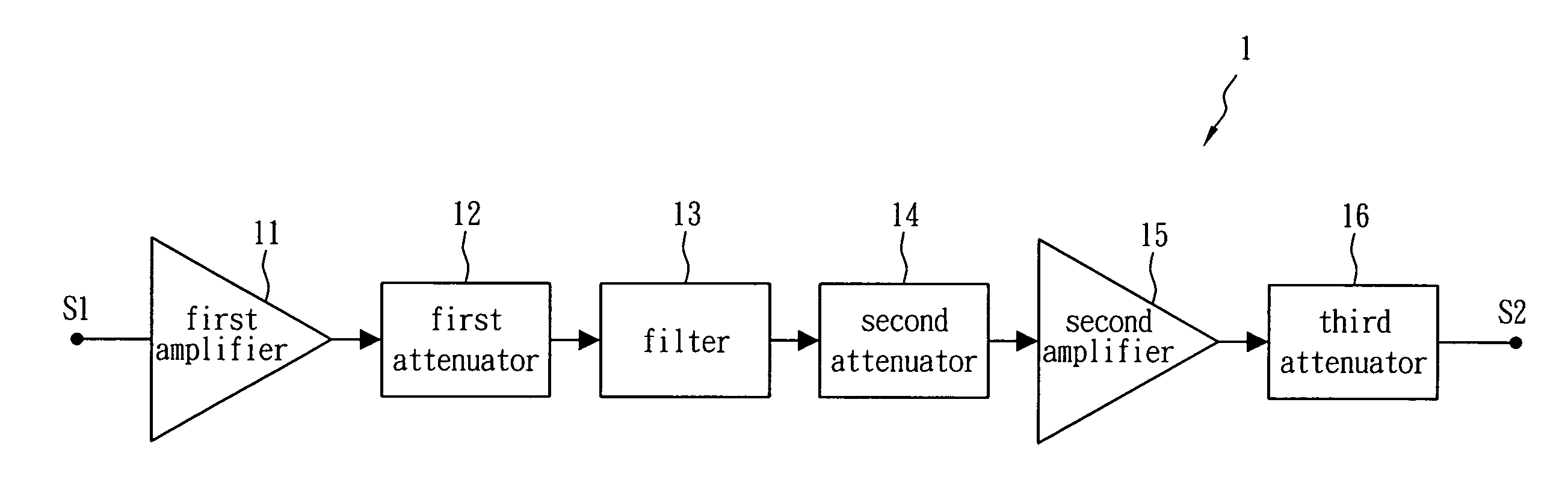
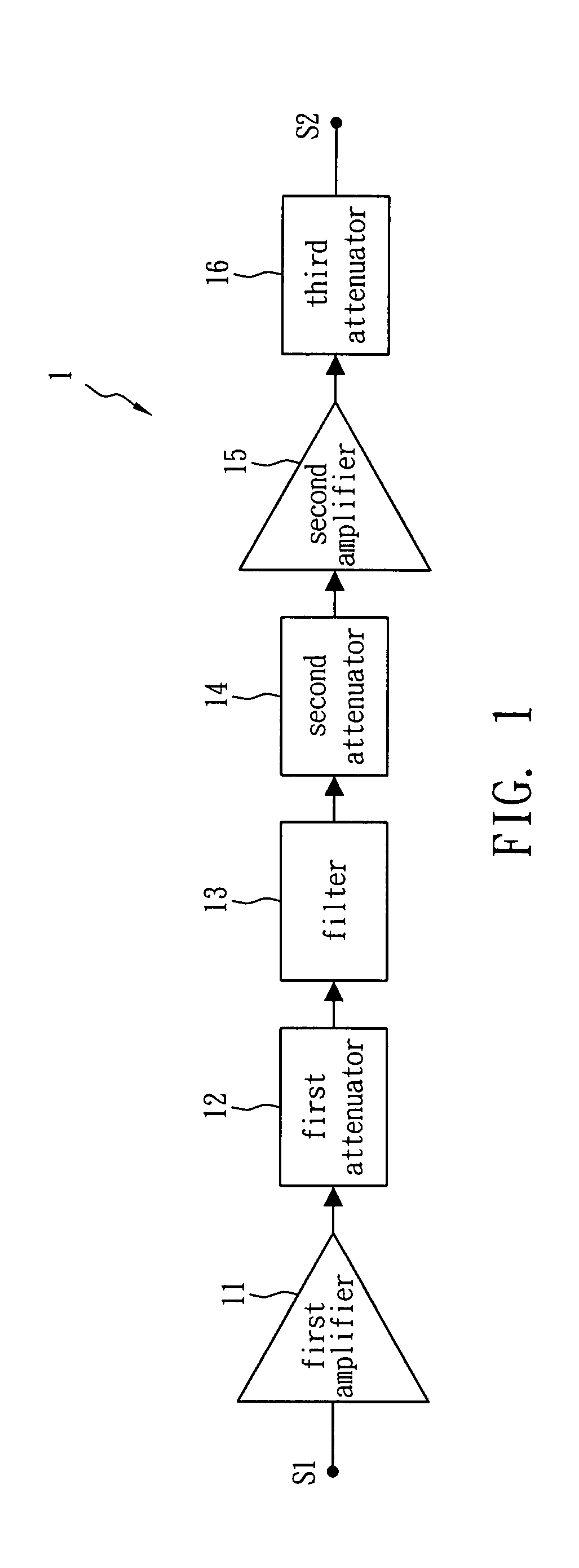
[0015]FIG. 1 shows a hint diagram of a gain compensation circuit 1 in accordance with one embodiment of the present invention. The gain compensation circuit 1 is applied to a microwave signal processor and includes a first amplifier 11, a first attenuator 12, a filter 13, a second attenuator 14, a second amplifier 15 and a third attenuator 16. The first amplifier 11 and the second amplifier 15 are used to amplify an input signal S1 of the microwave signal processor so as to generate an output signal S2. The filter 13 is disposed between the first amplifier 11 and the second amplifier 15 so as to remove noises created by the input signal S1 through the first amplifier 11 and the first attenuator 12. The second attenuator 14 is disposed between the filter 13 and the second amplifier, while the first attenuator 12 and the second attenuator 14 are used to reduce the return loss of the microwave signal processor. The third attenuator 16 is disposed behind the second amplifier 15 for redu...


PUM


Abstract

A gain compensation circuit comprises a first amplifier, a second amplifier, a filter, a first attenuator, a second attenuator and a third attenuator. The first amplifier is configured to amplify an input signal of the microwave signal processor. The filter is disposed between the first and second amplifiers. The first attenuator is disposed between the first amplifier and the filter for reducing return loss of the microwave signal processor. The second attenuator is disposed between the second amplifier and the filter for reducing return loss of the microwave signal processor. The third attenuator is electrically connected to the output of the second amplifier for reducing noise figure of the microwave signal processor and providing first and second gain compensations. The first gain compensation keeps the gain of the microwave signal processor constant under various temperatures, and the second gain compensation adjusts a nominal gain of the microwave signal processor.

Description

BACKGROUND OF THE INVENTION[0001]1. Field of the Invention[0002]The present invention relates to a gain compensation circuit, and more particularly to a gain compensation circuit applied to an outdoor microwave transceiver.[0003]2. Description of the Related Art[0004]Generally, the gain of a normal transceiver will decrease when it is operated at high temperature (about 40° C. to 60° C.), but increase at low temperature (below about 20° C.). Therefore, for some outdoor satellite transceivers which often operate in suboptimal environmental conditions, unless some gain compensation addressing temperature variation is performed, the gain of the transceiver will vary with the environmental temperature, causing signal distortion, and deteriorating communication quality. Therefore, it is common practice to design a compensation circuit which is able to suppress the gain of the transceiver at low temperature but enhance the gain of the transceiver at high temperature.[0005]As far as the ga...

Claims


Application Information

Patent Timeline
Patent Type & Authority Applications(United States)
IPC IPC(8): H01P1/22
CPCH03G1/0041
Inventor CHEN, RUEI YUENLIN, YEN FEN
Owner MICROELECTRONICS TECH INC
Why Eureka
Try Eureka